Class Specification Implementation Graph
This document discusses the combined utilization of white-box and black-box testing techniques through Class Specification Implementation Graphs (CSIG) to enhance software testing efficiency. The white-box techniques include control flow, data flow, branch, path, statement, and decision coverage testing. Conversely, black-box techniques such as decision table testing, equivalence partitioning, and boundary value analysis are also examined. By automating the construction process of CSIGs, testers can reduce maintenance efforts and generate test cases that address both specifications and source code, ensuring robust software quality.

Class Specification Implementation Graph
E N D
Presentation Transcript
Class SpecificationImplementation Graph By: NjumeNjinimbam Chi-Chang Sun
White Box testing • A software testing technique whereby explicit knowledge of the internal workings of the item being tested are used to select the test data. White box testing uses specific knowledge of programming code to examine outputs
White Box testing • Control flow testing • Data flow testing • Branch testing • Path testing • Statement coverage • Decision coverage
Black Box testing • Black-box testing is a method of software testing that tests the functionality of an application as opposed to its internal structures or workings (see white-box testing). This method of test can be applied to all levels of software testing: unit, integration, system and acceptance. It typically comprises most if not all testing at higher levels, but can also dominate unit testing as well.
Black Box testing • Decision table testing • All-pairs testing • State transition tables • Equivalence partitioning • Boundary value analysis • Control flow testing
Adjective • Sufficient testing requires both black- and white-box techniques. Although both tasks are similar in that they have the same objective, namely detecting faults within a program, often black- and white-box techniques are applied separately using different tools. The reason for this is the lack of techniques and tools integrating both tasks.
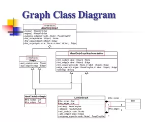
Object-oriented prototypes VS CSIG • Both approach relies on a graphical representation combining both specification and implementation of the class under test. Especially in control flow graph of the implementation by special data flow edges. • However, the major different is that CSIG can construction process can be automated.
Benefits • 1. The tester has only to be familiar with the concepts underlying one technique and needs training only for one tool. • 2. Less maintenance effort is required, since only one tool has to be maintained. • 3. Testing can be carried out more efficiently, since an integrated technique can generate test cases covering both the specification and the source code at the same time.
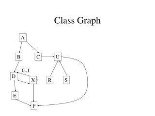
CSIG demonstration Edges • Intra- metho control and data flow edges • Inter-method control and data flow edges • CCFG frame edges
Step 1: Generating method implementation graphs • The first step consists of generating a control flow graph for each method based on its implementation. A control flow graph consists of nodes, representing statements, and edges, representing control flow among the statements. Moreover, the generated control flow graph can be augmented with data flow information for data flow testing.
Prototype of a transition • if (source) • if (guard) • action; • else throw new ErrorStateException(); • else throw new ErrorStateException();
CSIG construction cont'd • step 3- Generating method specification graphs • Step 4- Generating a CCFG frame • Step 5- Inserting the method graphs into a CCFG frame • Step 6- Adding data flow edges for black-box testing • The identification of def-use pairs for black- box testing can be carried out in 9 steps
Tool support - Using CSIGs for regression testing • Objective - provide confidence that modifications have the intended effect and do not affect other unchanged parts of the program. • selective regression testing - select those test cases from a given test suite covering changed parts of the program
Tool support - Using CSIGs for regression testing cont’d • selective regression testing technique proposed by Rothermel et al. [21] • main idea - compare two versions of a class and analyze the changes between these versions • In the original approach, class control flow graphs(CCFG) are used to compare the two version. • CCFG does not consider specification changes, we have adjusted their selection algorithm to be applicable to CSIGs
Tool support - Sample test process 1. Enter the specification of the class to be tested 2. Generation of executable test oracles 3. CSIG of the class is generated 4. User enters test cases needed for testing first version of the class. 5.Entered test cases are executed and results are compared to those obtained by the test oracle. • The tool also determines adequacy of the entered test cases
Tool support - Sample test process cont’d 6. Two modifications are made to the class. • first modification concerns its implementation • other modification concerns the specification 7. An executable test oracle and the CSIG are generated 8. The two CSIGs are compared using the modified selection algorithm 9. The test cases selected are executed.
Conclusions • Contrary to existing representation of classes, a CSIG is not restricted to the specification or implementation of a class.