Download
1 / 16
160 likes | 303 Views
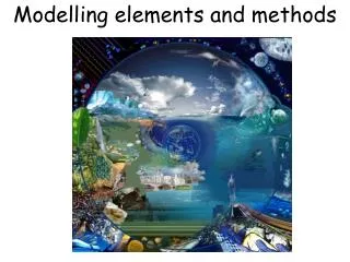
Constructive Methods in Modelling. Lecture 7 (Modelling). Surfaces of Revolution. Creates circular symmetric objects. Create a 3D surface by revolving a 2D profile curve around an axis of rotation in space. Closed profile curves generate closed surfaces. Examples:

E N D
Constructive Methods in Modelling Lecture 7 (Modelling)
Surfaces of Revolution • Creates circular symmetric objects. • Create a 3D surface by revolving a 2D profile curve around an axis of rotation in space. • Closed profile curves generate closed surfaces. • Examples: • Circular cylinder: The profile is a line segment parallel but not coincident with the axis of rotation. The closed version requires a rectangle. • Truncated cone: The line segment profile is slanted with respect to the axis.
Examples: Surfaces of Revolution • Torus: The profile is a circle inset in a plane aligned with the axis. • Complex circularly symmetric shapes: employ a Bézier or B-spline profile curve.
Generalized Cylinders • Extrusion: sweep a 2D shape along a (non-circular) path. • Some objects can be generated by extrusion or revolution. e.g. a cylinder (an extruded circle or a revolved line). • Generalized cylinders extend the concept of extrusions and surfaces of revolution to the extreme. • Total control over all sweep parameters. • But can produce degeneracies, e.g. self-intersection.
Generalized Cylinder Parameters • Can vary: • Cross Section – 2D shape does not have to be a circle and can change shape as it is swept. • Sweep Path – path does not have to be a straight line or revolution, can be any space curve. • Twist – the cross section can be rotated as it moves along the path • Scale – the size of the cross section can change along the path • Normal vector direction – conventionally the vector normal to the cross section points along the path, but even this can be varied • And any other parameters.
Spatial Deformation • Principle: • Indirectly deform an object by warping the surrounding space. • Jelly metaphor: • A shape is set within a block of jelly. • Flexing the jelly results in a corres- ponding distortion of the shape. • Mechanism: • Object vertices are embedded in a parametric hyperpatch, which is a 3D generalization of B-spline curves.
Free Form Deformation • Hyperpatch Equation: • Vertices (q) are expressed as a sum of control points (p)weighted by B-spline basis functions (b). • FFD Algorithm: • [1] Establish a (u,v,w) hyperpatch parameterization for all object vertices. • [2] Displace control points. • [3] Apply the hyperpatch equation.
Illustration of FFD Pre-Deformation Post-Deformation
Evaluation of FFD • Advantages: • Fast • Smooth, sculpted results • Variable scope • Disadvantages: • Lack of precise control • Screen clutter • Counter-intuitive • Later Developments: • Direct Manipulation with points or curves • Different deformation boundaries.
Constructive Solid Geometry • Constructive Solid Geometry (CSG) consists of regularized boolean set operations on closed 3D objects. • Boolean Set Operations Sphere (A) and Parallelepiped (B) Intersection Difference Union
CSG: Robustness • Regularized (represented by *): closed input objects produce a closed output object. • CSG arguments may be analytic (RT) or polygon mesh (PSC) objects (or both). • CSG is prone to special cases which cause robustness problems. • If points, edges, or faces of two polygon mesh arguments coincide an incorrect object may result. • For example, in modelling a gaming die, if the top of the cylindrical pips are flush with the cube surface then the difference may not be visible. • CSG is a huge area of research. Entire books have been written on this topic.
CSG Tree • CSG is evaluated as a pre-process in PSC and at run-time for RT. • The CSG tree is an effective structure for evaluating ray-object intersections. • Leaf nodes are objects. • Internal nodes are boolean operations.
CSG: Ray Tracing Algorithm Select an eye point and a screen plane FOR every pixel in the screen plane [num. pixels depends on image resolution] FOR every leaf node in the CSG tree compute and order by increasing depth the ray-object intersections. ENDFOR recurse left subtree returning intersection list [A] recurse right subtree returning intersection list [B] interleave sort A and B by increasing value along ray. FOR all entries in intersection list keep track of current state and use current intersection to access lookup table. ENDFOR RETURN new intersection list. ENDFOR A Intersection B
Constructive Modelling Exercise • Specify the steps required for construction of the jug pictured below. Note: some stages can be achieved in several different ways. Enumerate them where possible.
Constructive Modelling Solution • Jug: Surface of Revolution • Handle: Extrude Ellipse • Spout: Free-Form Deformation • Combination: Union of Deformed Jug and Handle