Download
1 / 41
660 likes | 1.34k Views
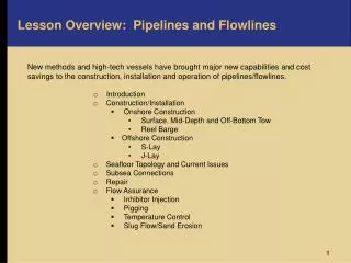
Lesson Overview: Pipelines and Flowlines. New methods and high-tech vessels have brought major new capabilities and cost savings to the construction, installation and operation of pipelines/flowlines. Introduction Construction/Installation Onshore Construction

E N D
Lesson Overview: Pipelines and Flowlines New methods and high-tech vessels have brought major new capabilities and cost savings to the construction, installation and operation of pipelines/flowlines. • Introduction • Construction/Installation • Onshore Construction • Surface, Mid-Depth and Off-Bottom Tow • Reel Barge • Offshore Construction • S-Lay • J-Lay • Seafloor Topology and Current Issues • Subsea Connections • Repair • Flow Assurance • Inhibitor Injection • Pigging • Temperature Control • Slug Flow/Sand Erosion
Introduction • In deep water, several factors increase pipeline/flowline cost and technology challenges.
Flowlines reach extreme depth and distance Subsea tiebacks are dominating deepwater development, reaching beyond 9,000 ft WD and almost 45 miles(oil) and 90 miles (gas) distance. GR-172
Learning Objectives • You will learn the current technology for deepwater pipeline/flowline: • Construction/installation • Repair • Seafloor Connection • Flow Assurance
What part do pipelines and flowlines play in offshore installations? Pipelines carry product, usually partially processed, from offshore facilities to shore. Flowlinestransport product produced from subsea wells, either to manifolds where it is commingled or directly to afloating facility. GR-14
Pipeline/flowline construction and installation methods • Onshore construction followed by towing to the offshore site by: • Surface tow • Mid-depth tow • Near-bottom tow Onshore construction plus winding on a reel and then unreeling offshore from a reel vessel • Offshore construction (on the pipelay vessel) and installation by: • S-lay • J-Lay We will now discuss each method.
Towing Pipelines on the Surface Pipelines can be fabricated on the beach, then towed out with buoyancy attached. When the buoyancy is reduced on location, and/or the pipe is flooded, it submerges. GR-44
Towing Pipeline Mid-Depth and Off-Bottom To prevent damage from wave forces, the pipeline may be towed submerged. • Off-bottom • Depth controlled by buoyancy and dragged chains • Mid-depth • Suspended between two boats GR-51
Onshore Flowline Construction and Laying from a Reel Vessel Smaller diameter line is fabricated onshore and then wound onto a large reel, as much as 200 ft in diameter. It is deployed offshorefrom a reel vessel, straightened as it is laid. GR-50 The first video (WV-10) is a horizontal reel vessel capable of laying two lines simultaneously. The second video (SS7-1) shows how the line is fabricated and loaded onto a vertical reel vessel.
S-Lay Technique for Laying Pipe In the illustrations and videos so far, we have seen pipe deployed from the vessel by the S-lay technique. The pipe releases horizontally from the back of the vessel and then bends downward over a stinger. Tension is maintained in the pipe, causing it to bend gently back to horizontal when it reaches the seabed. GR-45
S-Lay Stinger Stinger: A curved steel structure with rollers that protrudes from the stern of the pipelay vessel and limits the bending radius of the pipe GR-46
Construction and Deployment from an S-Lay Vessel The first animation (WV-9) illustrates how pipeline/flowline is fabricated and laid as the pipelay vessel moves along the prescribed route. This is a typical method for laying larger diameter pipelines. GR-169 The second video (WV-14), shows details of the fabrication and inspection operations on an actual pipelay vessel, the Solitaire. WV-9, WV-14
J-Lay Technique for Laying Pipe A more complex method, J-lay is generally employed for deep water due to the high tension caused by the weight of the long, suspended pipe. GR-47 The pipeline is fabricated vertically in a gimbaled tower and lowered vertically to the seabed where it bends to the horizontal (assuming a J curve). The tower is usually gimbaled to accommodate vessel motions without inducing bending stresses in the pipe.
J-Lay Technique, cont. Two of the largest crane barges in the world, Heerma Balder and Saipem 7000, (shown) have been retrofitted with J-lay towers. • GR-48 Saipem
J-Lay on Crane Barges, cont. • These huge crane barges can J-lay prewelded, 160-ft joints of pipe, reducing the number of welds required in the tower. Heerma GR-192 Saipem 7000 GR-194 The Heerma Balder can J-lay 30-in. diameter pipe in up to 10,000 ft water depth (2.6 MM lb). J-lay video: This (WV-8) animation shows how fabrication is accomplished in the vertical tower. Notice the multiple set of tractors for supporting the pipe’s weight.
Subsea 7 Ship • Like the Seven Borealis, below, some new vessels are equipped for both S-lay and J-lay. GR-164 The large pipelay vessel shown in this animation (SS7-2) is capable of both J- and S-Lay operations. Its large capacity and simultaneous operations capability gives it cost advantage for the installation of deepwater fields with extensive pipelines/flowlines.
Exercise Define the J-Lay technique for laying pipeline. Define the S-Lay technique for laying pipeline. What are the two kinds of barges used in pipeline construction? Why is deepwater pipeline construction so expensive? What are two methods of towing pipe?
Seafloor Topology The seafloor is often not flat and soft. Canyons, mounds, escarpments, even small mountains can present major obstacles for pipelines. GR-130 To avoid damage during pipe laying and to preclude long, unsupported spans, the seafloor must be surveyed to find a suitable pipeline route.
Seafloor Topology and Seafloor Currents In many areas there are significant currents at the seafloor. Hydrodynamic drag can move unburied pipeline on or near the seafloor. Unsupported spans are subject to Vortex Induced Vibrations (VIV) that can lead to fatigue failure. Orman Lange Pipeline Span GR-164 One of the worst seafloor challenges was the Orman Lange project offshore Norway, seen in this video (WV-25). Vibration monitors wereinstalled to record any vibration.
Seafloor Topology and Seafloor Currents, cont. When long spans and high seafloor currents are possible, the pipeline may be fitted with strakes to suppress VIV. GR-129 RJ Brown Even flowline jumpers may require strakes. RJ Brown GR-159a
Subsea Connections The ends of pipeline/flowlines are connected to seafloor facilities and wellheads by remote operations. Many ingenious techniques have been devised. Here are a few: Vertical Connections An illustration of a wellhead connected to a manifold with a jumper GR-162 GR-159 A subsea manifold connected to many wellheads
Subsea Connections – Vertical GR-163 1.The remote tools, carrying the ends of the jumper, are lowered over the upward-looking receivers. 2. The connectors are closed and sealed by hydraulic power. 3. The tools are retrieved.
Subsea Connections – Horizontal - I A previously laid line was terminated at a base with a guide post. First using the sleeve, then by fine positioning in the tool, the ends are merged. The connector is closed, sealed and tested.
Subsea Connections – Horizontal - II GR-161 A wire connected to the end of the new pipe pulls it close to the receiver on the facility. The ROV guides the pipe head into the receiver as the wire pulls it. The ROV then locks, seals and tests the connector.
Subsea Connections – Horizontal - III This animation (WV-31) shows an elaborate North Sea technique for seafloor joining of two pipeline segments. GR-170
Exercise Explain why and how a strake is employed. Give an example of ROV use in subsea connector utilities. 3. What is VIV and how can it be dealt with? 4. Describe how vertical or horizontal connectors can be employed remotely on the seafloor.
Repair A major challenge is repair of damaged deepwater pipelines. The schematic shows cutting out a section of the pipeline containing the damage, removing and replacing it with the help of an ROV*. * Remotely operated vehicle GR-4
Repair, cont. A crane lowers a section of pipeline for the repair. GR-78
Repair, cont. Chevron has developed and fabricated a deepwater pipeline repair system. It is stored on the Gulf coast for shipment when needed anywhere in the world. GR-166 This video (WV-19) explains the Chevron Deepwater Pipeline Repair System, which is similar to other operations.
Repair, cont. In the Chevron video, we saw that damaged pipeline needs to be cut and the ends prepared for insertion of a new section. The Wachs® Subsea diamond wire saw, deployed by an ROV, was used. GR-122 This is a (WV-23) demonstration of the Wachs diamond wire saw which is capable of cutting pipe up to 24-in. diameter.
Exercise Describe the principles of Chevron’s DW PR system. What is an ROV? How is an ROV instrumental in deepwater pipeline repair?
Flow Assurance All pipelines carrying crude oil and gas tend to become clogged, even on land and in shallow water. In deep water, low temperature and high pressure require various measures to assure pipeline flow. Very briefly, the problems are: • Gas hydrates are ice-like minerals that form crystals at the low temperatures and high pressures in the deep sea. Crystals forming inside pipelines or flowlines can clog the flow. • All crude oil contains some amount of wax (paraffin and asphaltene) that will solidify as the temperature drops. • Corrosion due to corrosive elements in the crude can damage or even breech the line.
Flow Assurance: Inhibitor Injection To prevent flow restrictions by hydrates and wax, and to inhibit corrosion, chemicals are injected into the flow. An extensive process is employed to specify the inhibitors and to design the injection system. GR-123
Flow Assurance: Pigging In addition to inhibition, pigs are pumped through lines to remove the buildup of hydrates, wax and scale on a pipeline’s inner wall.Instrumented pigs can also measure the pipeline wall thickness, detecting corrosion before leaking occurs. GR-125
Flow Assurance: Pigging, cont. • Pigging Operations: • Pig launchers and receivers must be built into the pipeline during construction. • A pig is pumped through the line, scraping the wall and pushing the buildup out through the pig receiver. GR-167 This video (WV-24) of the Pipeline Engineering Automatic Pig Launching System illustrates pig launching and retrieval.
Flow Assurance: Temperature Control For long flowlines carrying very hot product from very deep wells, chemical injection and pigging may be insufficient or not cost effective. Another option is to reduce heat loss by coating flowlines with insulation. Constructed “pipe-in-pipe” uses the outer pipe to protect the insulation against the harsh environment of installation and seabed survival. Extensive design analysis and testing are required. GR-168 Courtesy Bredero Shaw
Flow Assurance: Temperature Control, cont. Pipe-in-pipe construction protects the insulation during installation and in service. GR-128 Designs of pipe-in-pipe insulated flowlines requires extensive thermal analysis and testing.
Flow Assurance: Temperature Control, cont. Complex pipe-in-pipe designs can incorporate fluid and electrical heating sources to deal with highly viscous oil. GR-187
Flow Assurance: Slug Flow and Sand Erosion Two additional problems are slugsin two-phase flow (liquid and gas) and sand erosion. Solutions to these problemsare more difficult in remote, deep water. Slug Flow Liquid collects at depressions in the pipe, cleared only when the gas pressure behind it builds up sufficiently. Uneven flow results. Rising and falling pressure causes pipe vibration and disruptive conditions at the pipe exit. An active system of pressure sensors and variable chokes may be required to break up the slugs. GR-124
Flow Assurance: Challenging Example • Anadarko’s new Independence Hub platform in 8,000 ft WD presents a major challenge to uninterrupted hydrocarbon flow. • 20+ tiebacks (totaling over 176 miles) • Farthest tieback: 45 miles • Deepest wellhead: 9,000 ft WD • Pipeline: 135 miles to near shore terminal GR-135 Underwater view of Independence Hub in the GoM shows its flowlines and risers.
Exercise 1. What natural occurrences impede pipeline flow? 2. What is a pig and how does it solve a problem in pipeline flow? 3. How can insulating the pipe help pipeline flow? 4. What is pipe-in-pipe insulation? 5. How did Anadarko solve its flow problems at great depths?