Download
1 / 17
170 likes | 281 Views
R & D Status of Lost Alpha Measurement - Development of Scintillators M. Nishiura, M. Isobe, N. Kubo, T. Hirouchi, M. Sasao, K. Shinto, M. Okamoto, S. Kitajima, and S.V. Konovalov NIFS, Tohoku Univ. and Kurchatov Institute. OUTLINE Concept and System Candidates

E N D
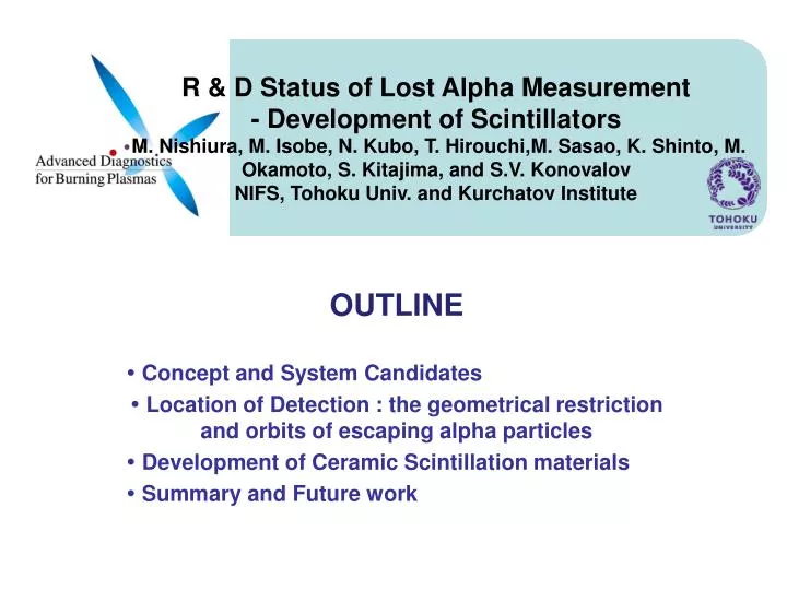
R & D Status of Lost Alpha Measurement- Development of Scintillators M. Nishiura, M. Isobe, N. Kubo, T. Hirouchi,M. Sasao, K. Shinto, M. Okamoto, S. Kitajima, and S.V. KonovalovNIFS, Tohoku Univ. and Kurchatov Institute • OUTLINE • Concept and System Candidates • Location of Detection : the geometrical restriction and orbits of escaping alpha particles • Development of Ceramic Scintillation materials • Summary and Future work
Concept and System Candidates Candidates of Measurement Tools Points- measurement : Energy and pitch-angle resolved Faraday-cup detectors, Scintillator probes, Bolometric Imaging (Peterson et al.) Loss imaging: IR camera imaging, Camera imaging of scintillators on the FW Gamma Ray (Kipty et al.)
Requirements to the System Sensors selective sensitivity to alpha particles, low sensitivity to other ions, neurons, electrons stable at high temperature (~ 700 K), wide dynamic range and linearity, mechanical endurance under conditions of high temperature and radiation exposure. Signal types and transfer-methods should be considered. Faraday-cup detectors - current (micro A-mA) Scintillator probes - 400 - 600 nm Bolometric Imaging (IR) Loss imaging: IR camera imaging (IR) Camera imaging of scintillators on the FW - 400 - 600 nm
Heat Load (kW/m2) port #16 #17 Probes (FC, Schintillator,Bolometric) Location of Detection : the geometrical restriction The CAMERA upper port 11 Camera imaging:The upper port 11 is used for the viewing camera, and the ceramic scintillators are fixed using blanket gaps and slit, or extra shallow pits. Probes : better to be installed on the bottom of the port plug. viewing FW Ceramic Schintillator
A A Location of Detection : the geometrical restriction EXAMPLE A: Ceramic Schintillators are fixed in holes on the top end of FW (Cu backing) of the BM #17 and view from the upper port camera. viewing alpha X Be FW Ceramic Schintillator
Orbit calculation for Detector position A The detector position A, is not good, by two reasons. 1) Drift orbits might not touch the wall surface ? (should be confirmed ). 2) The poloidal angle of the lost position is not the best A A A
Orbit calculation for Detector position B Detector position B : Moving upward poloidally along the slits on the BM #16, drift orbits cover wider area of returning position. Those might be suitable to observe the MHD loss. There might be possibility to observe alpha losses with probes on the bottom of port plug. However, the coverage of wider area of poloidal angle is needed as the basic understanding. Extra Holes
Development of Ceramic Scintillation materials Two applications Scintillator probesCamera imaging of scintillators on the FW The required properties of a scintillation plate to be used on ITER are as follows: high sensitivity to alpha particles, low sensitivity to other ions, neurons, electrons, gamma rays, stable emission at high temperature (~ 700 K), Wide dynamic range and liniearity, mechanical endurance under conditions of high temperature and radiation exposure. No-irradiation damage It had been known that the sensitivity of ceramic scintillator diminishes under high temperature, above 100o C. The characteristics of ceramic sheets in which scintillation materials are blended have been tested.
Mix scintillation materials, ceramic bond, and H2O Dry in room temperature Baking in vacuum at T>150 ℃ Y3Al5O12:Ce ※ceramic bond Y3Al5O12:Ce Scintillation plates The reference : ZnS(Ag) which is deposited on the glass plate is tested. LHD lost ion probe uses this type. Fabrication of ceramic-like Scintillation plates
Bombardment by p, 4He, at 1- 100 nA Irradiation stage is equipped with Optical Fiber head to a spectrometer (PM-1) FC, CCD camera Heaters, thermo-couples Scintillator test chamber Irradiation experiment at 4.5 MV-Dynamitron(FNL) at Tohoku Univ. Scinntillator test chamber Scintillator Heater and thermo couple Beam transport line 4.5MV-Dynamitron Spectrometor
Experimental results for the ceramic-like scintillators - preheated at 150 ℃ The linearity of the emission intensity to the beam influx is good up to > 4x10¹² ions/(cm2 s). Typical influx expected at ITER is ranging in 1012 ~ 1014 ions/(cm2 s) But the degradation was observed soon after one minute beam irradiation. Typical video image for Y3Al5O12:Ce with Aron ceramic Results from 3MeV H+, He+ Beam bombardment Synergetic Effect of Temperature and Irradiation Beam intensity changed.
Before beam irradiation, the heat treatment up to 450 ºC had been carried out for two hours. YAG:Ce He+ beam current (nA) ◇36.50,□37.10,△37.05,◇36.65,□34.25,△35.6,◇35.25,□35.75 Flux ~1.8x 10¹² ions/(cm2 s) The substrate temperature keeps constant at 17 ºC during the beam irradiation. ZnS:Ag He+ beam current (nA) ◇34.25,□36.00,△36.50,◇34.00 room temperature Irradiation damage of YAG:Ce and ZnS:Ag at the room temperature YAG:Ce 0 160 Irradiation time (min.) ZnS:Ag 0 30 Irradiation time (min.)
Before beam irradiation, the heat treatment up to 450 ºC had been carried out for two hours. From above equations, the time constant of the degradation can be obtained astwo=77, and tw=100. After a year operation, t=107/60 min, the intensity degradation with baking becomes smaller than that without baking. It is found that the emission intensity becomes 0.33 of the original. Effect of pre-heating treatment on the irradiation degradation. YAG:Ce withAaron ceramic
YAG:Ce 450 ºC, two hours baking before experiments ZnS:Ag 400 ºC, two hours baking before experiments He+ beam current (nA) ◇38.00,□36.50,△36.00 After the irradiation, the degradation of the fluorescent intensity is observed. Dependence of emission for YAG:Ce and ZnS:Ag on temperature YAG:Ce ZnS:Ag Present data From Z. Lin et al. PPPL TM392
Studies of ITER integration for several systems are started. Ceramic-like schintillation-material can be fixed in shallow pits on the FW, and viewed from the upper port camera of #11. Probes for energy and angle-resolved measurement, Faraday-cup detectors, scintillator probes, Bolometric Imaging detectors can be installed in the bottom of diagnostic ports. Full-gyro orbit calculations including realistic detector designs and detailed 3D FW shapes, are needed, and now under preparation. The ceramic schintillators newly developed were tested with 1-3 MeV alpha beam and the linearity of the emission intensity to the beam influx is good up to > 4x10¹² ions/(cm2 s). Typical influx expected at FW of ITER is ranging in 1012 ~ 1014 ions/(cm2 s) Summary and Future work
The ceramic schintillators newly developed were tested with 1-3 MeV alpha beam. The test under high temperature shows that the efficiency of some ceramic schintillators does not change on temperature upto 300 ºC, but changes by dose accumulation. Irradiation effect is large for ZnS:Ag, but less for a ceramic-like schintillators of YAG:Ce, and it becomes stronger by preheating treatment. -> One year operation of ITER corresponds to continuous bombardment of flux of 140 min.:1.8x 10¹² ions/cm2 /s, total fluence:9x10¹⁷ ions/(cm2) . Our present experimental test showed that degradation of emission efficiency of a ceramic-like schintillators of YAG:Ce is less than 33%. A experiment to test improvement by heating recovering treatment is planned. Summary and Future work