Download
1 / 32
400 likes | 951 Views
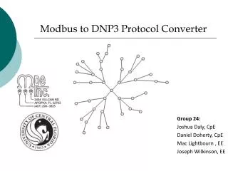
Modbus to DNP3 Protocol Converter. Group 24: Joshua Daly, CpE Daniel Doherty, CpE Mac Lightbourn , EE Joseph Wilkinson, EE. Modbus vs. DNP3. Project motivation: MPE needs to allow for communication between network nodes that are using these different protocols. . Four-Semester Plan.

E N D
Modbus to DNP3 Protocol Converter Group 24: Joshua Daly, CpE Daniel Doherty, CpE Mac Lightbourn , EE Joseph Wilkinson, EE
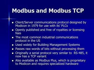
Modbus vs. DNP3 Project motivation: MPE needs to allow for communication between network nodes that are using these different protocols.
Four-Semester Plan Phase I Device Build User Interface Initialization Phase II Network Communications Security
Key Specs • Operates between -10 and 80 degrees Celsius • Protects against surges of 120 V • MCU clock has a backup battery that can power the MCU for 12 hours if power is lost • Sends alarm to master device when power is lost • Takes Ethernet input and gives Ethernet output • Allows user to view and change networking parameters • Logs 20,000 events, even when power is lost, with 98% fidelity • Records date and time of each event to millisecond accuracy • Notifies master device of all events with 95% fidelity
Firmware Overview • Menu system • Allows user to adjust stored parameters • Strict requirements from the sponsor • Creation of data Structs to maintain parameters • Initializing the device • Handle all button functionality
Coding Environments • Visual Studio • Used while PCB board was in development • Familiar environment • Code Warrior • Freescale MCU • Optimization of .s19 file
Data Storage • Stored in the EEPROM • Storage requirements • Factory defined • User defined
Buttons • Required Guidelines • Button Functionality • Menu Navigation • Time Delayed press
Screen • Display Screen • 3 7-segement displays • Mimic the current display used by MPE • Allows user to visually navigate and set parameters
Power Supply Requirements Takes in 24 V DC • This supply is shared with other components in the lift station control panel • This is a low voltage in comparison to other devices being used in industrial applications • The low voltage bypasses some of the testing requirements for meeting UL standards
Power Supply Requirements Surge Protection • Must handle currents up to 80 mA • Must correct irregular voltages • Multiple devices are connected in a shunt configuration for combined benefits
Power Supply Requirements Must be fed through a DIN rail mount • All devices in the lift station control panel attach to one rail • Mount also serves as chassis ground for added surge protection
DC/DC Converter • Voltage is stepped down to 3.3 V and then fed to the power plane • To conserve power, a passive switching regulator was chosen • Our configuration is a common circuit with extensive application notes
Testing Why do we test?
Testing • Power Up • The three 7-segment LEDs must synchronously display each number for 100 (+/- 25) milliseconds from 0-9 in ascending order within 2 seconds after power up. • The menu scroll LED must illuminate for 1 (+/- 0.1) second within 2 seconds after power up. • The value change LED must illuminate for 1 (+/- 0.1) second within 2 seconds after power up. • The power LED must illuminate within 1 second after power up.
Testing • Button Scroll • When operating in menu scroll mode, the three 7-segment LEDs must display the parameter number with the following format where XX is a parameter number between 00 and 99: P.XX. • The displayed parameter list must circle to the beginning of the list when cycled up at d.06 • The displayed parameter list must circle to the end of the list when cycled down at E.01
Testing • Sleep/Wake • The user interface LEDs must not remain illuminated if all user interface inputs are inactive for 120 (+/- 2) seconds. • When in a state of inactivity, the unit must transition to a state of activity • The state of user action must be preserved when the user interface LEDs are extinguished due to inactivity. • The state of user action must be reinstated when the unit returns from an inactive state.
Challenges • How does it all work • Hardware challenges • Firmware challenges