Download
1 / 66
1.5k likes | 3.15k Views
Ceramic Capacitors . NIC PRODUCT TRAINING. Topics: Leaded and Surface Mount (SMT) Characteristics Ceramic Dielectrics Substitution Guides Styles - Appearance - Dimensions NIC Part Numbers Competition Cross Reference Use in Circuit Board Assembly Buzzwords & Technical Info.

E N D
Ceramic Capacitors NIC PRODUCT TRAINING
Topics: Leaded and Surface Mount (SMT) • Characteristics • Ceramic Dielectrics • Substitution Guides • Styles - Appearance - Dimensions • NIC Part Numbers • Competition Cross Reference • Use in Circuit Board Assembly • Buzzwords & Technical Info PRODUCT TRAINING: Ceramic Capacitors
Capacitor Family Tree CAPACITORS ELECTROSTATIC ELECTROLYTIC FILM CERAMIC ALUMINUM TANTALUM DISC MLC SMT MONO PRODUCT TRAINING: Ceramic Capacitors
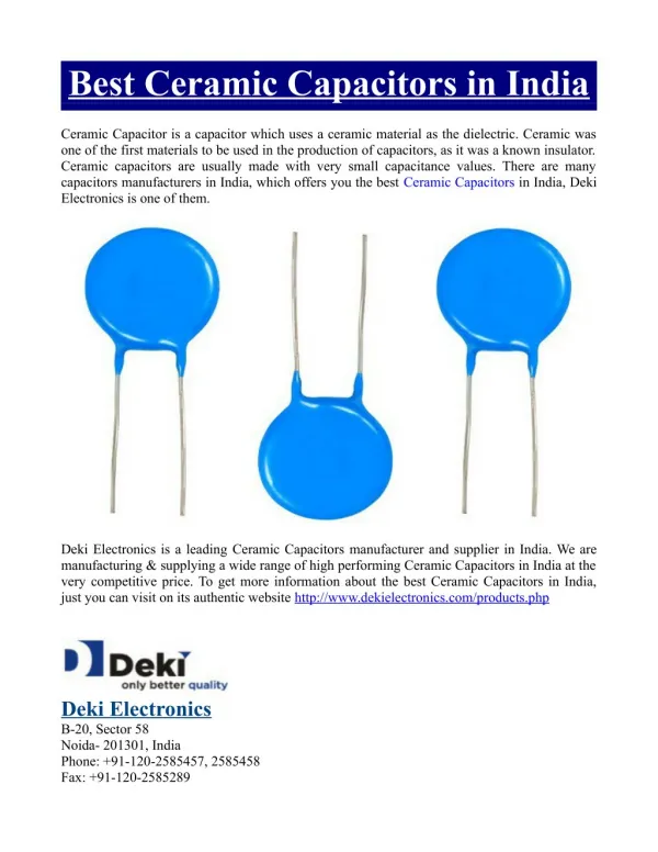
Ceramic Characteristics C • Ceramic capacitors belong to the family of ELECTROSTATIC capacitors. They have the following characteristics: • They are Non-Polar • They dominate the lower range of capacitance values • They are the most widely used style of capacitor (Largest Volume & Lowest Pricing) • They are available in both leaded and surface mount styles • The vast majority are fixed capacitance value(their value is not user variable) PRODUCT TRAINING: Ceramic Capacitors
Capacitance (Cap) Value Characteristic C 0.1uF Capacitance Valuein… pF = pico-Farad = 1 x 10-12 F = 0.000000000001F NIC offers ceramic capacitors with values ranging from… 0.5pF ~ 22,000,000pF ( = 22uF) Most call outs are from 10pF ~ 0.1uF PRODUCT TRAINING: Ceramic Capacitors
Cap Value Characteristic 0.1uF Capacitance Valuein… pF = pico-Farad = 1 x 10-12 F = 0.000000000001F nF = nano-Farad = 1 x 10⁻⁹ F = 0.000000001F uF = micro-Farad = 1 x 10⁻⁶ F = 0.000001F 1000pF = 1nF 1,000,000pF = 1000nF = 1uF PRODUCT TRAINING: Ceramic Capacitors
Cap Value Characteristic 0.1uF Capacitance ValueRange Low End: pF Typical Values: 1pF, 4.7pF, 22pF, 100pF, 330pF, 1000pF, etc. MediumRange: nF Typical Values: 1nF, 10nF(0.01uF), 100nF (0.1uF), 220nF (0.22uF), etc. High End: uF Typical Values: 1uF, 2.2uF, 10uF and 22uF PRODUCT TRAINING: Ceramic Capacitors
Cap Value Characteristic • Standard Capacitance Values: (PER EIA-575 & RS 460) • E12 • 10 12 15 18 22 27 33 39 47 56 68 82 • Examples: • 1.0, 1.2, 1.5,…. 10, 15, 22,… 100, 180, 270,… 1K, 3.3K, 4.7K,… • 10K, 33K, 56K,… 100K, 220K, 680K,… 1uF, 2.2uF, 4.7uF,… PRODUCT TRAINING: Ceramic Capacitors
Cap Value Characteristic • Standard Capacitance Values: (PER EIA-575 & RS 460) • E24 • 10 11 12 13 15 16 18 20 22 24 27 30 33 36 39 43 47 51 56 62 68 75 82 91 In-between Values Shown In Red Are Considered “Odd” Non-Preferred Values And As Such Are Not Stocked And Should Be Discouraged From Being Selected... PRODUCT TRAINING: Ceramic Capacitors
Tolerance Characteristic 0.1uF ±20%(M) Capacitance Tolerance Capacitance value will have tolerance value (+25°C): ±1% (F), ±2% (G), ±5% (J), ±10%(K), ±20%(M) and +80%/-20%(Z) ±0.1pF(B), ±0.25pF(C) and ±0.5pF(D) These are the most commonly called out tolerances PRODUCT TRAINING: Ceramic Capacitors
Tolerance Characteristic Capacitance Tolerance Target Value Tolerance -10% -5% 0 +5% +10% This “Bell” curve illustrates product yield J K 50 60 70 80 120 130 140 150 90 95 100 105 110 Capacitance (pF / nF / uF) PRODUCT TRAINING: Ceramic Capacitors
Component Substitution Guideline Capacitance Tolerance Substitution “A component with a tighter (better) tolerance can replace a looser (worst) tolerance component.” i.e... ±1%(F) tolerance part can replace ±2%(G), ±5%(J) or ±10% (K) tolerance part i.e... ±2%(G) tolerance part can replace ±5%(J), ±10% (K) or ±20% (M) tolerance part i.e... ±5%(J) tolerance part can replace ± 10%(K) or ±20% (M) tolerance part i.e… ±10%(K) tolerance part can replace ±20%(M) or +80%/-20%(Z) tolerance part i.e… ±20%(M) tolerance part can replace +80%/-20%(Z) tolerance part PRODUCT TRAINING: Ceramic Capacitors
Voltage Characteristic 0.1uF ±20%(M) 50VDC Voltage Rating NIC offers ceramic capacitors with voltage ratings from… 16VDC ~ 15,000VDC Most call outs are from 25V ~ 100VDC PRODUCT TRAINING: Ceramic Capacitors
Component Substitution Guideline Voltage Rating Substitution “A component with a higher voltage rating may be used in place of, or as a substitute for, a lower voltage rated component.” i.e… 1000V rated part can replace 500V, 250V or 100V rated part. i.e… 500V rated part can replace 250V , 100V or 50V rated part. i.e… 250V rated part can replace 100V, 50V or 25V rated part. i.e… 100V rated part can replace 50V or 25V rated part. i.e… 50V rated part can replace 25V or 16V rated part. i.e… 25V rated part can replace 16V or 10V rated part. PRODUCT TRAINING: Ceramic Capacitors
TC Characteristic Unfortunately not all capacitance values can be produced from one ceramic dielectric formulation… A wide range of ceramic dielectrics are needed, and have been developed, to cover a broad range of capacitance values. The EIA (Electronics Industries Alliance) established industry classifications for ceramic dielectrics that are agreed to and met by all ceramic capacitor producers. These ceramic dielectric classifications are identified by their temperature coefficient (TC) code. Y5F Y5P X7R Z5U NPO PRODUCT TRAINING: Ceramic Capacitors
TC Characteristic TEMPERATURE RANGE +10% 000 -10% -20% -30% CAPACITANCE CHANGE LIMITS Room Temperature is +25°C (77°F) All capacitors are specified (and guaranteed) with regards to their capacitance value and tolerance at +25°C All capacitors will change in capacitance value if their temperature departs from room temperature (through heating or cooling within an electronic circuit). Blue line shown on above graph illustrates capacitance change over -50°C to +100°C temperature range. The maximum allowable change in capacitance over a specified operating temperature range is the Temperature Coefficient (TC) of the capacitor. -50C +25C +100C PRODUCT TRAINING: Ceramic Capacitors
TC Characteristic Standard Temperature Coefficients (TC) of ceramic capacitors: X7R= ±15% C over -55°C ~ + 125°C PRODUCT TRAINING: Ceramic Capacitors
TC Characteristic * MLC = Multi-Layer Ceramic Industry standard Temperature Coefficients (TC) of ceramic capacitors: X5R = ±15% C over -55°C ~ +85°C X7R= ±15% C over -55°C ~ +125°C Standard Tolerance: K = 10% Y5F = ±7.5% C over -30°C ~ +85°C Y5P = ±10% C over -30°C ~ +85°C Y5R = ±15% C over -30°C ~ +85°C Y5S = ±22% C over -30°C ~ +85°C Y5T = +22% / -33% C over -30°C ~ +85°C Y5U = +22% / -56% C over -30°C ~ +85°C Y5V= +22% / -82% C over -30°C ~ +85°C Standard Tolerance: Z = -20%/+80% Z5U= +22% / -56% C over -10°C ~ +85°C Standard Tolerance: M = 20% Z5V = +22% / -82% C over -10°C ~ +85°C COG = NPO =0±30PPM/ °C over -55°C ~ + 125°C NPO = 0±30PPM/ °C over -55°C ~ + 125°C Standard Tolerance: J = 5% GENERAL PURPOSE: FAIR PERFORMANCE OVER TEMPERATURE, VOLTAGE, FREQUENCY AND TIME Most Common MLC* Call-Outs ULTRA -STABLE OVER TEMPERATURE, VOLTAGE, FREQUENCY AND TIME PRODUCT TRAINING: Ceramic Capacitors
TC Characteristics +10% 0 -10% -20% -30% -50C +25C +100C SPECIAL TEMPERATURE COMPENSATING TC’S (linear capacitance value change over temperature) N150 = -150PPM ±60PPM/ °C over -30°C ~ + 85°C N470 = -470PPM ±60PPM/ °C over -30°C ~ + 85°C N750 = -750PPM ±120PPM/ °C over -30°C ~ + 85°C N1500 = -1500PPM ±250PPM/ °C over -30°C ~ + 85°C N3300 = -3300PPM ±500PPM/ °C over -30°C ~ + 85°C SL = -330PPM±500PPM/ °C over -30°C ~ + 85°C These temperature compensating TC’s are available in CERAMIC DISC CAPACITOR styles... PRODUCT TRAINING: Ceramic Capacitors
Component Substitution Guideline • Temperature Coefficient “A component with a more stable (better) temperature characteristic (TC) can replace a less temperature stable (worse) component. i.e…an X7R ceramic can replace Z5U or Y5V ceramic parts. i.e…an NPO ceramic can replace a X7R or Z5U or Y5V ceramic. NPO… X7R… X5F… X5P… X5R… XRS… X5T… Y5U… Y5V… Z5U… Z5V... MOST STABLE LEAST STABLE PRODUCT TRAINING: Ceramic Capacitors
Styles - Appearance (Leaded) Radial Leaded “Mono” Axial Leaded “Mono” Radial Leaded Ceramic Disc Monolithic Multi-layer Ceramic (MLC) Packaged on tape for auto insertion PRODUCT TRAINING: Ceramic Capacitors
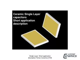
Single Layer Disc Capacitor (Radial) NCD Series SINGLE LAYER CERAMIC DIELECTRIC DISC Disc Ceramic Nippon SILVER ELECTRODE PRINTED AND FIRED ON BOTH SIDES Y5F 102K 1KV LEADS ATTACHED TO EACH ELECTRODE PROCETIVE COATING APPLIED AND COMPONENT MARKED PRODUCT TRAINING: Ceramic Capacitors
Ceramic Disc Capacitor (Radial) Body Diameter From 4mm to 25mm (0.15”~1.0”) NCD Series Disc Ceramic Nippon Y5F 102K 1KV Lead Spacing 6.35mm (0.25”) is standard (bulk packaged) 5.0mm (0.2”) is standard (Tape and Reeled “T/R”) 7.5mm (0.30”) and 10mm(0.39”) are options PRODUCT TRAINING: Ceramic Capacitors
Ceramic Disc Capacitor (Radial) NCD Series Disc Body Thickness From 2mm to 7mm (0.079” ~ 0.276”) Ceramic Nippon Lead Diameter 0.6mm (0.024”) is standard… On larger body diameters 0.8mm (0.031”) lead diameter is available as option. It is also standard on 5KVDC and higher voltage ratings. PRODUCT TRAINING: Ceramic Capacitors
Ceramic Disc Capacitor (Radial) PRODUCT TRAINING: Ceramic Capacitors
Part Numbering System NIC NCD Series - Ceramic Disc Capacitor NCD102M1KVZ5UDTR Tape and Reel Optional Lead Forming: No Code = Straight Leads C, D, E, J, K = Crimped Leads Temperature Coefficient: 15 TCs Available Voltage Rating (VDC) : 12V ~ 15KV Capacitance Value Tolerance: F = ±1%, G = ±2%, J = ±5%, K = ±10%, M = ±20% and Z = +80%/-20% Capacitance Value in pF: 0.5pF ~ 0.22uF (3 digit code) First 2 digits are significant. Third digit is number of zeros. 100 = 10pF, 101 = 100pF, 332 = 3300pF, 103 = 10,000pF = 0.01uF Values less than 10pF R = decimal 1R0 = 1.0pF, 4R7 = 4.7pF Series PRODUCT TRAINING: Ceramic Capacitors
Capacitance Range per TC NIC NCD Series - Ceramic Disc Capacitor Temperature Coefficients: PRODUCT TRAINING: Ceramic Capacitors
Capacitance Range per TC NIC NCD Series - Ceramic Disc Capacitor Temperature Coefficients: PRODUCT TRAINING: Ceramic Capacitors
Capacitance Range per TC NIC NCD Series - Ceramic Disc Capacitor NPO SL N150 & N470 N750 ~ N3300 Y5F Y5P Y5R & Y5S & Y5T Z5U & Z5V Y5V 1pF 10pF 100pF 1nF 10nF 100nF 1uF 0.001uF 0.01uF 0.1uF 1uF CODE: 1R0 100 101 102 103 104 105 PRODUCT TRAINING: Ceramic Capacitors
Cross Reference Ceramic Disc Capacitor Cross Reference - TECATE PRODUCT TRAINING: Ceramic Capacitors
Multilayer Ceramic Capacitors (MLC) SINGLE LAYER CERAMIC DIELECTRIC SHEET SILVER ELECTRODE PRINTED MULTILAYER CERAMIC SHEETS STACKED PRODUCT TRAINING: Ceramic Capacitors
Multilayer Ceramic Capacitors (MLC) MULTILAYER CERAMIC SHEETS PRESSED, FIRED AND CHIP ELEMENT TERMINATED 1 2 3 4 5 MULTIPLE LAYERS CONSTRUCTION RESULTS IN MULTIPLE INCREASE IN CAPACITANCE SURFACE AREA = INCREASED CAPACTANCE VALUE Example above shows five times increase in capacitance as compared to single layer PRODUCT TRAINING: Ceramic Capacitors
Multilayer Ceramic Capacitors (Leaded) AXIAL LEADED MULTILAYER CERAMIC CAPACITOR RADIAL LEADED MULTILAYER CERAMIC CAPACITOR LEAD WIRE EPOXY RESIN COATING EPOXY RESIN COATING SOLDER LEAD WIRE SOLDER NCM Series NCMA Series PRODUCT TRAINING: Ceramic Capacitors
MLC Ceramic Capacitor (Radial) NCM Series Multilayer Ceramic Nippon Body Width 3.8mm ~ 12.7mm (0.15” ~ 0.50”) Lead Diameter 0.5mm = 0.020” 0.63mm = 0.025” Body Height 3.8m ~ 12.7mm (0.15” ~ 0.50”) Lead Spacing 2.54mm = 0.1” 5.1mm = 0.2” 10.2mm = 0.4” Body Thickness 2.54mm ~ 5.1mm (0.1” ~ 0.2”) PRODUCT TRAINING: Ceramic Capacitors
MLC Ceramic Capacitor (Radial) NIC NCM Series - Radial Leaded Multilayer Ceramic Capacitor Part Marking PRODUCT TRAINING: Ceramic Capacitors
Part Numbering System NIC NCM Series - Radial Leaded Multilayer Ceramic Capacitor NCM21X7R104K50TR Tape and Reel Voltage Rating (VDC) : 50V, 100V & 200V Capacitance Value Tolerance: F = ±1%, G = ±2%, J = ±5%, K = ±10%, M = ±20% and Z = +80%/-20% Capacitance Value in pF: 1.0pF ~ 2.2uF (3 digit code) First 2 digits are significant. Third digit is number of zeros. 100 = 10pF, 101 = 100pF, 332 = 3300pF, 103 = 10,000pF = 0.01uF Values less than 10pF R = decimal 1R0 = 1.0pF, 4R7 = 4.7pF Temperature Coefficient: NPO, X7RandZ5U Size: 15, 20, 21, 30, 40 and 50 Series PRODUCT TRAINING: Ceramic Capacitors
Capacitance Range per TC NIC NCM Series - Radial Leaded Multilayer Ceramic Capacitor Temperature Coefficients: NPO X7R Z5U 1pF 10pF 100pF 1nF 10nF 100nF 1uF 10uF CODE: 1R0 100 101 102 103 104 105 106 PRODUCT TRAINING: Ceramic Capacitors
MLC Ceramic Capacitor (Axial) NCMA Series Axial Multilayer Ceramic Body Length 4.32mm ~ 10.2mm (0.17” ~ 0.4”) Nippon Lead Diameter 0.5mm (0.020”) Body Diameter 2.54mm ~ 3.81mm (0.1” ~ 0.15”) PRODUCT TRAINING: Ceramic Capacitors
MLC Ceramic Capacitor (Axial) NIC NCMA Series - Axial Leaded Multilayer Ceramic Capacitor Part Marking PRODUCT TRAINING: Ceramic Capacitors
Part Numbering System NIC NCMA Series - Axial Leaded Multilayer Ceramic Capacitor NCMA10Z5U104M50TR Tape and Reel Voltage Rating (VDC) : 50V, 100V & 200V Capacitance Value Tolerance: F = ±1%, G = ±2%, J = ±5%, K = ±10%, M = ±20% and Z = +80%/-20% Capacitance Value in pF: 1.0pF ~ 1.0uF (3 digit code) First 2 digits are significant. Third digit is number of zeros. 100 = 10pF, 101 = 100pF, 332 = 3300pF, 103 = 10,000pF = 0.01uF Values less than 10pF R = decimal 1R0 = 1.0pF, 4R7 = 4.7pF Temperature Coefficient: NPO, X7RandZ5U Size: 10, 11, 20, 30, and 40 Series PRODUCT TRAINING: Ceramic Capacitors
Capacitance Range per TC NIC NCMA Series - Axial Leaded Multilayer Ceramic Capacitor Temperature Coefficients: NPO X7R Z5U 1pF 10pF 100pF 1nF 10nF 100nF 1uF 10uF CODE: 1R0 100 101 102 103 104 105 106 PRODUCT TRAINING: Ceramic Capacitors
Cross Reference Leaded Multilayer Ceramic Capacitor Cross Reference: PRODUCT TRAINING: Ceramic Capacitors
Styles - Appearance (Surface Mount) SMT Ceramic Chip Monolithic Multi-layer Ceramic Chip (MLC) 7” AND 10” REELS Packaged on tape for auto insertion PRODUCT TRAINING: Ceramic Capacitors
Multilayer Ceramic Capacitors SINGLE LAYER CERAMIC DIELECTRIC SHEET SILVER ELECTRODE PRINTED MULTILAYER CERAMIC SHEETS STACKED PRODUCT TRAINING: Ceramic Capacitors
Multilayer Ceramic Capacitors (MLC) MULTILAYER CERAMIC SHEETS PRESSED, FIRED AND CHIP ELEMENT TERMINATED 1 2 3 4 5 MULTIPLE LAYERS CONSTRUCTION RESULTS IN MULTIPLE INCREASE IN CAPACITANCE SURFACE AREA = INCREASED CAPACTANCE VALUE Example above shows five times increase in capacitance as compared to single layer PRODUCT TRAINING: Ceramic Capacitors
Multilayer Ceramic Capacitors TIN PLATE FINISH NICKEL BARRIER LAYER SILVER BASE CERAMIC DIELECTRIC NMC Series Chip Multilayer ceramic Nippon PRODUCT TRAINING: Ceramic Capacitors
Dimensions (Surface Mount) English Metric Length Width 0402 1005 1.0mm (0.04”) 0.5mm (0.02”) 0603 1608 1.6mm(0.06”) 0.8mm (0.03”) 0805 2012 2.0mm (0.08”) 1.2mm (0.05”) 1206 3216 3.2mm (0.12”) 1.6mm (0.06”) 1210 3225 3.2mm (0.12”) 2.5mm (0.10”) 1812 4532 4.5mm (0.18”) 3.2mm (0.12”) 2225 5764 5.7mm (0.22”) 6.4mm (0.25”) WIDTH LENGTH PRODUCT TRAINING: Ceramic Capacitors
Reel Labeling System PRODUCT TRAINING: Ceramic Capacitors
Part Numbering System NIC NMC Series - Multilayer Ceramic Chip Capacitor NMC0603X7R104K16TRP Tape and Reel Voltage Rating (VDC) : 16V, 25V 50V, 100V, 200V, 500V and 1KV Capacitance Value Tolerance: F = ±1%, G = ±2%, J = ±5%, K = ±10%, M = ±20% and Z = +80%/-20% Capacitance Value in pF: 0.5pF ~ 22uF (3 digit code) First 2 digits are significant. Third digit is number of zeros. 100 = 10pF, 101 = 100pF, 332 = 3300pF, 103 = 10,000pF = 0.01uF Values less than 10pF R = decimal 1R0 = 1.0pF, 4R7 = 4.7pF Temperature Coefficient: NPO, X7R, Y5V andZ5U Size: 0402, 0603, 0805, 1206, 1210, 1812 and 2225 Series NMC (Standard) , NMC-E (Low Profile), NMC-H (High Voltage) and NMC-Q (High Q NPO) PRODUCT TRAINING: Ceramic Capacitors
Capacitance Range per TC NIC NMC Series - Multilayer Ceramic Chip Capacitor Temperature Coefficients: NPO X7R Y5V Z5U 0.5pF 1pF 10pF 100pF 1nF 10nF 100nF 1uF 10uF PRODUCT TRAINING: Ceramic Capacitors