Download
1 / 30
300 likes | 418 Views
Electric field distribution in irradiated MCZ Si detectors. E. Verbitskaya , V. Eremin, I. Ilyashenko Ioffe Physico-Technical Institute of Russian Academy of Sciences St. Petersburg, Russia Z. Li Brookhaven National Laboratory, Upton, NY, USA J. Härkönen

E N D
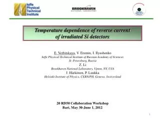
Electric field distribution in irradiated MCZ Si detectors E. Verbitskaya, V. Eremin, I. Ilyashenko Ioffe Physico-Technical Institute of Russian Academy of Sciences St. Petersburg, Russia Z. Li Brookhaven National Laboratory, Upton, NY, USA J. Härkönen Helsinki Institute of Physics, CERN/PH, Geneva, Switzerland Marko Mikuž, Vladimir Cindro Jožef Stefan Institute, Ljubljana Chris Parkes Glasgow University 9 RD50 Collaboration Workshop CERN, Geneva, Oct 16-18, 2006
Outline 1. Background: E(x) distribution in heavily irradiated detectors 2. Approach for simulation of detector Double Peak response and E(x) profile reconstruction with a consideration of electric field in the “neutral” base 3. Comparison of experimental results on DP pulse response of MCZ Si detectors irradiated by 1 MeV neutrons and 24 GeV protons with F > 1014 cm-2 (detectors developed under “Technotest” sub-project) 4. Simulation of DP E(x) profile with a consideration of carrier trapping to midgap energy levels 5. Reconstruction of E(x) profiles in MCZ Si detectors Conclusions E. Verbitskaya et al., 9 RD50 Workshop, CERN, Geneva, Oct 16-18, 2006
Models for electric field distribution in irradiated Si detectors n-type Si beyond SCSI -Neff Standard model Neff = const, E(x) – linear, Vfd derived from C-V curves Valid for F 5·1013 cm-2 E. Verbitskaya et al., 9 RD50 Workshop, CERN, Geneva, Oct 16-18, 2006
Models for electric field distribution in heavily irradiated Si detectors Bulk Si: n-type converts to high resistivity p-type E. Borchi, M. Bruzzi et al, IEEE Trans. Nucl. Sci. 46 (1999) 834; M. Bruzzi, IEEE Trans. Nucl. Sci. 48 (2001) 960. Detector: Double Junction structure: Two depleted regions at the sides of detectors irradiated beyond SCSI, peaks of E at p+ and n+ contacts Z. Li, H. W. Kraner, IEEE TNS 39 (1992) 577 Two depleted regionsand a neutral base in-between D. Menichelli, M. Bruzzi, Z. Li, V. Eremin, NIM A 426 (1999) 135 Two depleted regionsand a base in-between with electric field due to potential drop over high resistivity bulk E. Verbitskaya et al. Operation of heavily irradiated silicon detectors in non- depletion mode. Pres. RESMDD’05, Nucl. Instr. and Meth. A 557 (2006) 528-539 E. Verbitskaya et al., 9 RD50 Workshop, CERN, Geneva, Oct 16-18, 2006
Experimental evidence of Double Peak electric field distribution A. Castaldini, A. Cavallini, L. Polenta, F. Nava, C Canali, NIM A476 (2002) 550 Measurements of OBIC and surface potential in non-irradiated and irradiated detectors Existence of two depletion layers adjacent to the contacts and separated by a layer inverted to p-type Si (close to intrinsic) Insignificant difference in E(x) near the p+ contact in non-irradiated and irradiated Si detectors Model of DP E(x) distribution: ionization of DLs due to band bending near the contacts E. Verbitskaya et al., 9 RD50 Workshop, CERN, Geneva, Oct 16-18, 2006
Origin of Double Peak (DP) electric field distribution V. Eremin, E. Verbitskaya, Z. Li. NIM A 476 (2002) 556 -V Trapping of free carriers from detector reverse current to Deep Levels leads to DP E(x) midgap DLs: DD: Ev + 0.48 eV DA: Ec – 0.52 eV trapping E. Verbitskaya et al., 9 RD50 Workshop, CERN, Geneva, Oct 16-18, 2006
n+ p+ E2 E1 hn Eb W1 Wb W2 Approach for pulse response simulation and E(x) reconstructionwith a consideration of electric field in the base Goal: reconstruction of electric field profile from current pulse response, simulation of detector DP pulse response • Three regions of heavily irradiated detector structure are considered • Reverse current flow creates potential difference and electric field in the neutral base Transient current: Neff, Ntr = f(F) E. Verbitskaya et al. Pres. RESMDD’05, NIM A 557 (2006) 528-539 E. Verbitskaya et al., 9 RD50 Workshop, CERN, Geneva, Oct 16-18, 2006
n+ p+ i ~ exp(-t/teff) QW2 tcol Simulation of pulse response for carrier generation from one side of detector Signal due to carrier drift in W1 is independent on the properties of Wb and W2 i = i1 ~ exp(-t/teff) W1, Neff1, E1 Eb, Wb tcol: depends on Eb and Wb Charge collected inside W2 Wb, W2, E2, Neff2 QW2 = Qo(d – W1 –Wn)/d Edx = V E. Verbitskaya et al., 9 RD50 Workshop, CERN, Geneva, Oct 16-18, 2006
Experimental tool for study of electric field distribution Transient Current Technique Pulse Laser for generation of nonequilibrium carriers Short wavelength of laser (e or h generation from one side and transport through detector bulk) E. Verbitskaya et al., 9 RD50 Workshop, CERN, Geneva, Oct 16-18, 2006
Experimental observations of DP current pulse response 1. 1 MeV neutron irradiation MCZ Si, Fn = 51014 cm-2 • Electron collection (p+ side): second peak (H2) increases with V: H1/H2 • Major junction at n+ side: SCSI: E. Verbitskaya et al., 9 RD50 Workshop, CERN, Geneva, Oct 16-18, 2006
2. 24 GeV proton irradiation MCZ n-Si, Fp = 11015 cm-2 Double Peak for all detectors at V > 200 V 1st peak dominates (H1/H2>1) Influence of processing: difference in H1/H2 E. Verbitskaya et al., 9 RD50 Workshop, CERN, Geneva, Oct 16-18, 2006
DP response under long term annealing MCZ Si, Fp = 11015 cm-2 PTI-CZ-e4 Tann = 80C, 7 steps Before anneal 2: 35 min (total tann) 3: ~1.5 h 5: 6 h 6: 12 h 7: 18 h • H1 and H2 rise at each step • H1/H2changes under annealing and 1 V = 40-440 V E. Verbitskaya et al., 9 RD50 Workshop, CERN, Geneva, Oct 16-18, 2006
Evolution of Double Peak response under annealing,MCZ Si, Fp = 11015 cm-2 Normalized response teff doesn’t change under annealing E. Verbitskaya et al., 9 RD50 Workshop, CERN, Geneva, Oct 16-18, 2006
Amplitude ratio H1/H2 under annealingMCZ Si, Fp = 11015 cm-2 Stages of DP shape non-monotonous changes: 1. increase of H1 2. increase of H2 shape tends to single peak (E(x) linear) at tann = 1.5-6 h 3. reduction of H2 and increase of pulse width E. Verbitskaya et al., 9 RD50 Workshop, CERN, Geneva, Oct 16-18, 2006
Comparison between n and p: amplitude ratio H1/H2 in DP response Fluence: Fn = 51014 cm-2 Fp = 11015 cm-2 ≤1 E. Verbitskaya et al., 9 RD50 Workshop, CERN, Geneva, Oct 16-18, 2006
neutrons Comparison: MCZ Si, Q(V) protons 1e14 cm-2 5e13 cm-2 1e15 cm-2 5e14 cm-2 Double peak Single peak annealing
Experimental data on Neff(F) and Vfd dependence in MCZ Si detectors b for neutrons and protons, TCT data FZ, n: 0.022 MCZ, n: 0.017 MCZ, p: 0.0045 Z. Li et al.Radiation hardness of high resistivity magnetic Czochralski silicon detectors after gamma, neutron, and proton radiations, TNS- 51 (2004) 1901-1908 A. Bates and M. Moll. A comparison between irradiated Magnetic Czochralski and Float Zone silicon detectors using the Transient Current Technique. NIM A 555 (2005) 113 Depletion voltage has passed its minimum value without type inversion E. Verbitskaya et al., 9 RD50 Workshop, CERN, Geneva, Oct 16-18, 2006
E(x) profile in MCZ Si detectors irradiated by 24 GeV protons (earlier results) Pulse response fit and E(x) reconstruction basing on three region structure Fp = 2.21015 cm-2 Electron collection (p+ side) SMART detector M. Scaringella et al. Localized energy levels generated in MagneticCzochralski silicon by proton irradiation andtheir influence on the sign of space chargedensity. NIM A, in press; and N. Manna, pres. 8 RD50 Workshop, June 25-28, 2006, Prague Wide region with positive space charge! “Puzzle” – Space Charge Sign in MCZ Si irradiated by 24 GeV protons?? E. Verbitskaya et al., 9 RD50 Workshop, CERN, Geneva, Oct 16-18, 2006
Simulation of DP E(x) profile with a consideration of carrier trapping to midgap energy levels: E(x) and Neff(x) vs. V • Parameters: • introduction rate of generation centers mj • introduction rate of midgap deep levels, DA and DD • concentrationratio k = NDA/NDD bias voltageV temperature T detector thickness d • initial resistivity (shallow donor concentration No) midgap DLs: DD: Ev + 0.48 eV simulation is based on • DA: Ec – 0.52 eV Shockley-Read-Hall statistics E. Verbitskaya et al., 9 RD50 Workshop, CERN, Geneva, Oct 16-18, 2006
Simulation: Evolution of Double Peak E(x) at various NDA/NDDFn = 51014 cm-2 V: 100-1000 V No = 11012 cm-3 d = 300 mm, RT E. Verbitskaya et al., 9 RD50 Workshop, CERN, Geneva, Oct 16-18, 2006
E(x) and Neff vs. VFn = 51014 cm-2 Neff is vastly non-uniform and E is non-linear even at maximal V of 1000 V E. Verbitskaya et al., 9 RD50 Workshop, CERN, Geneva, Oct 16-18, 2006
Evolution of Double Peak E(x) vs. NDA/NDDFn = 51014 cm-2 No = 3.51012 cm-3 d = 300 mm, RT MCZ Si E at p+ contact changes insignificantly: correlates to neutron irradiation Major junction at p+ side: correlates to proton irradiation E. Verbitskaya et al., 9 RD50 Workshop, CERN, Geneva, Oct 16-18, 2006
Experimental results: current response fit and E(x) reconstructionin MCZ Si detectors • Goal: • simulation/fit of detector DP pulse response, • reconstruction of electric field profile from current pulse shape, considering detector structure with three regions: W1, Wb and W2 E. Verbitskaya et al., 9 RD50 Workshop, CERN, Geneva, Oct 16-18, 2006
E(x) reconstruction and adjustment to midgap level modelNeutrons,Fn = 51014 cm-2, MCZ Si PTI-CZ-d11 At high Fn and V negative SCR extends inside detector bulk Parameters derived by adjustment: mj = 0.7 cm-1 DDEv + 0.48 eV 5·1014 cm-3 DAEc - 0.52 eV 6.75·1014 cm-3 k = 1.35 E. Verbitskaya et al., 9 RD50 Workshop, CERN, Geneva, Oct 16-18, 2006
n+ p+ E2 E1 Eb Wb W2 W1 Reconstruction of E(x) from DP response:influence of processing p+ Fn = 51014 cm-2 Electric field gradient dE/dx and Neff in the region adjacent to p+ contact are different and sensitive to detector processing E. Verbitskaya et al., 9 RD50 Workshop, CERN, Geneva, Oct 16-18, 2006
Reconstruction of E(x) from DP response:Protons, Fp = 11015 cm-2, MCZ Si + annealing 360 V 200 V annealing E. Verbitskaya et al., 9 RD50 Workshop, CERN, Geneva, Oct 16-18, 2006
E(x) reconstruction and adjustment to midgap level modelFp = 51014 cm-2, MCZ Si, PTI-CZ-e4 Parameters derived by adjustment: mj = 0.7 cm-1 – like for neutrons DDEv + 0.48 eV 6.6·1014 cm-3 DAEc - 0.52 eV 3·1014 cm-3 k = 0.45 k(n)/k(p) 3 correlates to b(n)/b(p) 4 E. Verbitskaya et al., 9 RD50 Workshop, CERN, Geneva, Oct 16-18, 2006
Protons, Fp = 11015 cm-2, MCZ Si, annealing • In MCZ Si detectors irradiated by 24 GeV protons electric field extends over entire detector thickness. The major junction is at the p+ contact and SCR is charged positively. • Under annealing E(x) profile becomes more symmetric with increasing V. E. Verbitskaya et al., 9 RD50 Workshop, CERN, Geneva, Oct 16-18, 2006
Conclusions Approach of E(x) distribution with a consideration of electric field in the base region allows E(x) reconstruction in detectors irradiated by high F irrespective to the irradiation type. In heavily irradiated detectors electric field distribution is vastly non-uniform and shows double peak shape with positively and negatively charged regions. Full depletion implies that electric field extends over entire detector bulk and carrier collection is drift process. • Different balance of DDs and DAs induced by neutrons and protons results in the essential difference of E(x) profile, pulse shape and collected charge at the same bias voltage. In neutron irradiated MCZ Si detectors E at the major junction (n+ side) decreases with voltage that is favorable for detector operation. In MCZ Si detectors irradiated by 24 GeV protons the major space charge region is adjacent to the p+ contact and has a positive space charge. E. Verbitskaya et al., 9 RD50 Workshop, CERN, Geneva, Oct 16-18, 2006
Acknowledgements • This work was supported in part by: • RD50 collaboration, • INTAS-CERN project # 03-52-5744, • RFBR project SS # 00-15-96750 Thank you for your attention! E. Verbitskaya et al., 9 RD50 Workshop, CERN, Geneva, Oct 16-18, 2006