Download
1 / 59
590 likes | 785 Views
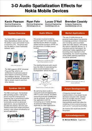
Design of CMOS Current Amplifier using Transimpedance & Transconductance Blocks. Supervisor Dr. Adnan Harb Student ID Asma Abdullah 199904242 Azza Ahmad 199902208 Rania Jaber 199902201 Wedad Al-Kaabi 199902203. Presentation Outline. IC’s design flow

E N D
Design of CMOS Current Amplifier using Transimpedance & Transconductance Blocks Supervisor Dr. Adnan Harb Student ID Asma Abdullah 199904242 Azza Ahmad 199902208 Rania Jaber 199902201 Wedad Al-Kaabi 199902203
Presentation Outline • IC’s design flow • Simulation results in phase I • Characterization of RM and GM circuits • Characterization of the current amplifier • Design the layout of the current amplifier • Standard, Safety and Feasibility cost study • Gantt chart
IC design flow Design Specification Schematic Capture Create Symbol Simulation
Simulation results in phase I • All transistors of the RM and the GM circuits were ON and most of them were in the saturation region. • The DC level at the output of: • The RM circuit was 1.19 mV. • The GM circuit was 11.2 µA . • The obtained gain in the RM circuit was 92.8 dB with phase margin of 60o . • The dynamic range: • (-5µA to 5µA) possible input current of the RM circuit . • (-0.5V to 0.5V) possible input voltage of the GM circuit .
Before Connecting RM and GM circuits…. • Certain characterizations of the two amplifiers were checked: • Dynamic range. • The output impedance of the RM with the input impedance of the GM.
1. Was the dynamic range of the RM within the dynamic range of the GM?
The dynamic range of the (RM) Input current range (-5µA - 5µA) Output voltage range (-250mV – 250mV)
The dynamic range of the (GM) Input Voltage range (-500mV – 500mV)
The output voltage range of the RM is within the input voltage range of the Gm … GM RM OUTPUT voltage Range ( -250mV to 250mV) INPUT voltage Range (-500 mV to 500 mV )
2. Was the input impedance of the GM smaller than the output impedance of the RM?
The load impedance of the Rm The load impedance
The input impedance of the Gm Input transistors
After Connecting RM and GM circuits … Was the connection done Properly?
Faced problem The error was in the PMOS transistor (MP1) in both RM blocks. It was not converging. Solution A resistor was added (R = 1Meg) in parallel with the current source (I 1)
Simulation error: No convergence in MP1 Solution: Adding R=1MΩ The RM circuit
After Connecting RM and GM circuits…. • Certain characterizations of the whole current amplifier were checked: • The frequency Response: • Gain. • Phase margin. • The dynamic range . • The region of operation of transistors. • Power dissipation .
Frequency Response • The Gain Gain= 47.9 dB (249.4 (A/A))
Frequency Response • The phase margin Phase margin = 89o
The dynamic range The output range -2.5 mA, 2.5mA The input range -10μA, 10μA
The Dynamic range using the Fourier Transform …. • The transient analysis
The Fourier Transform of the differential output of the current amplifier • The FFT of the transient signal Spectrum of the Fundamental Frequency Third harmonic
Study the affect of the temperature (-40oC, 27 oC, 125 oC) on the linearity of the current amplifier
The affect of the different temperatures in linearity for 100 KHz.
The affect of the different temperatures in linearity for 100 KHz. Dynamic Range of CMOS amplifier ( 100 kHz ) 100 80 - 40 oC 60 Harmonic distortion (dB) 27 oC 40 125 oC 20 0 0 50 100 150 Input Current(uA)
The affect of the different temperatures in linearity for 1 MHz.
Dynamic Range of CMOS amplifier (1MHz) 90 80 70 60 Harmonic distortion (dB) 50 27o C 40 125oC 30 20 10 0 0 20 40 60 80 100 Input Current(uA) The affect of the different temperatures in linearity for 1 MHz.
Power dissipation • The power dissipated in the circuit was determined using PSpice simulator, it was 41.4 mWatts.
IC design flow Design Specification Schematic Capture Create Symbol Simulation Layout Stick diagram Transistor scaling Transistor implementation
What is the layout ? • Layout is the lowest level of design abstraction for VLSI • Layout is the sketch of transistors level connections. Why is the layout ? • Layout is very time consuming and complex. • The size of the layout determine the cost to manufacture the circuit • The shape of elements in the layout determine the speed of the circuit
What is a stick diagram ? • The stick diagram is a cartoon or sketch of the layout • It makes the design of the layout easier and faster • The different components were represented as follow: • Metal 1 blue lines • p- Diffusion yellow lines • N-diffusion green lines • VDD & VSS blue rectangular • Contacts blue squares • Polysilicon red lines
Contact Polysilicon Metal1 NMOS PMOS RM Stick diagram VDD MP5 MP1 MP3 MP6 MP2 MP4 RM out I out MN1 MN4 MN2 MN6 MN8 MN3 MN5 MN7 MN9 VSS
VDD VREF MP4 MP3 MP1 MP6 MP5 Vin1 MP2 Vin2 Vin2 OUT2 OUT1 MN7 MN1 MN5 MN3 Contact metal1/metal2 Polysilicon Metal1 MN4 MN6 MN2 MN8 NMOS PMOS VSS Metal2 GM Stick diagram
N-diffusion D Poly silicon D G S S NMOS Layout NMOS Transistor P-diffusion S Poly silicon D G S PMOS Layout PMOS Transistor D NMOS and PMOS layouts
Design rules • Layout is the sketch of transistors level connections. • Govern the layout of individual components and the interactions-spacing and electrical connections between components. • Determine the low-level properties of chip designs. • In Electric software the design rule is scaled with λ of 0.2µm.
How the design rule applied? MP1 100µm 1µm MP1 500 λ 5 λ
50 5 Techniques used (Transistor scaling) w w w L L L W ……n L Example: 50 50 500 λ 5 5 ……10 5 λ
Transistor scaling GM transistor scaling RM transistor scaling
VDD Contacts VSS PMOS NMOS Contacts PMOS NMOS Metal-2 Transistor Implementation… Connection between the two types of transistor The contact between VDD and the body of the transistor Metal 2 connection
MN1 Transistor Implementation… Transistor MN1
MP1 RM Layout MN1
GM Layout MP4 MN2
IC design flow Design Specification Schematic Capture Create Symbol Simulation Layout DRC – Design Rule Check
Design rule check (DRC) • The design rule check (DRC) tool is used to check for minimum spacing and minimum size and to ensure that combinations of layers form legal components.
IC design flow Design Specification Schematic Capture Create Symbol Simulation Layout DRC – Design Rule Check Extraction LVS – Layout Versus Schematic Check Post-Layout Simulation