Download

1 / 3
30 likes | 368 Views
Antisymmetric RMF Current Drive in FRCs R.D. Milroy, H.Y. Guo, A.L. Hoffman, and L.C. Steinhauer Redmond Plasma Physics Laboratory, University of Washington Abstract

E N D
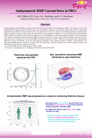
Antisymmetric RMF Current Drive in FRCs R.D. Milroy, H.Y. Guo, A.L. Hoffman, and L.C. SteinhauerRedmond Plasma Physics Laboratory, University of Washington Abstract Rotating Magnetic Fields (RMF) can be used to both form and sustain Field Reversed Configurations (FRC). The addition of even a small simple transverse magnetic field to an FRC tends to open the field lines, leading to a concern that confinement could be compromised. Calculations show that both electron and ion orbits are confined due to the cyclic nature of the field line opening, but rapid electron thermal conduction remains a concern unless the edge density can be maintained extremely low. It was shown1 that if an antisymmetric RMF is applied, the field lines remain closed for small ratios of vacuum RMF B to external axial magnetic field Be. Recent experiments show improved confinement when antisymmetric RMF is applied, and an analysis of these results2 shows that field lines remain closed for much larger ratios of B/Be due to fact that the RMF only partially penetrates the FRC. With these encouraging results, antisymmetric RMF will soon be tested further on the new TCS upgrade experiment. We extend the analysis to include a representation of the antisymmetric RMF that more accurately accounts for the antenna geometry, study the sensitivity of the results to precise symmetry, and determine the threshold for the opening of field lines. 1 S. A. Cohen and R. D. Milroy, Phys. Plasmas, 7, 2539, (2000) 2 H. Y. Guo, A. L. Hoffman, and L. C. Steinhauer, Phys. Plasmas 12, 062507 (2005) But, symmetric transverse RMF still tends to open field lines Field lines only partially penetrate the FRC Antisymmetric RMF was proposed as a means of achieving field-line closure Calculations by Cohen & Milroy showed that for full penetration, B/Be must be < 5% to achieve field-line closure using anti- symmetric RMF. For RMF driven FRCs in TCS, B/Be > 25%,which would be too high. However, it has been demonstrated in TCS that, due to shallow RMF penetration, it is possible to maintain the field lines closed, even with relatively strong RMF magnitudes.
Overall performance is improved with antisymmetric RMF Temperatures are generally higher at lower densities because effects of radiation are smaller. But, there is a consistency in the higher temperatures achieved with antisymmetric RMF. No increase in absorbed RMF power. • Anti-// operation results in same average density, but higher fields are reached due to presumably higher achieved temperature. Energy confinement is improved Antisymmetric higher magnetic fields Energy confinement time: cc = EFRC / Pnet In steady state: Pnet= Prmf – Prad – Pcx– Pi = Pcond + Pconv RMF penetration remains similar, sothe RMF torque,TRMF B2 *,is unchanged. But higher fields and greater fluxes are generatedwith anit-// RMF: 0.5 mWb – // RMF : 0.77 mWb – anti-// RMF. Field-Line tracking with partially penetrated RMF Basic FRC structure: 2D Grad-Shafranov equilibrium (Steinhauer). RMF radial structure: based on an analytical model for partially penetrated RMF (Hoffman). RMF axial structure: specified with either an even parity (// RMF) or an odd parity (anti-// RMF). Normal (symmetric) RMF: Field lines are open, striking end wall, with a connection length: Lcon ~ 2.5LFRC. Antisymmetric RMF: Field lines are kept closed even at edge, r = 0.9rs.
Contours of field line length vs. starting position Contours of max. radial extent vs. starting position Field-Line tracking with a new model A new model uses a numerically generated equilibrium and RMF that fully penetrates near the ends. An n=1 Br / Bz component added to include the effects of current return at midplane and antenna ends. A full mapping of where field lines are open has been calculated. Effect of axial asymmetry If the RMF is not symmetric with respect to the FRC, field lines are opened again. Consider a case with the RMF shifted axially by rs/3 with respect to the FRC. Field lines are long – but they do open. Contours of field line length vs. starting position Contours of max. radial extent vs. starting position Imposed n=1 RMF Symmetric fields Antisymmetric fields Calculate field line length as function of starting position in the x-y plane. All field lines start at z=0. Inner “brown” region contains closed field lines. If separatrix is close to wall, field lines originating near the axis of symmetry will strike the wall. Standard Calculation: Bω / Bz0= 0.25, δ*/rs = 0.15(corresponding to experiment) When the same analysis is applied to normal symmetric RMF, all of the field lines are opened. Contours of field line length vs. starting position Contours of max. radial extent vs. starting position Summary It has been demonstrated experimentally, that energy confinement is dramatically improved when FRCs are formed and sustained with antisymmetric RMF. Calculations show that, with partial penetration, field lines can be closed when antisymmetric RMF is used. Partial penetration allows field lines to remain closed for much higher amplitude RMF than previously predicted for full penetration (Cohen and Milroy). An antiparallel antenna configuration will be used on the new TCS upgrade facility, which will allow higher temperatures to be achieved. 3D projection of field lines (length = 50 rs), with a) started along the x and b) started along the y axis.