Download
1 / 49
490 likes | 659 Views
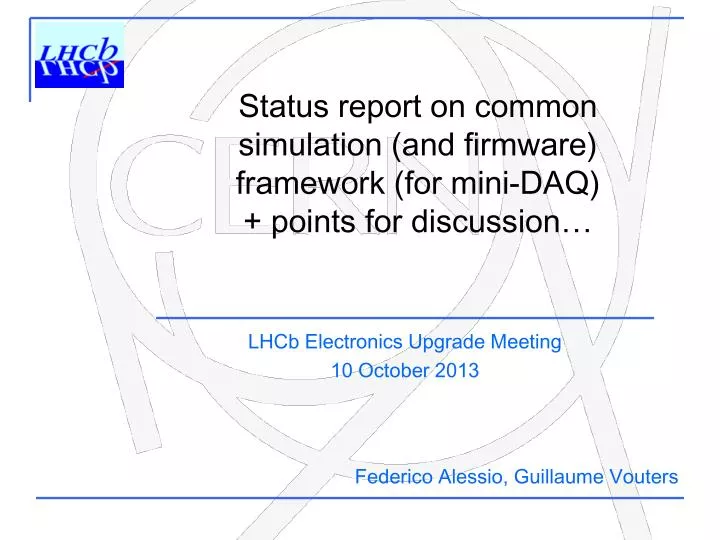
Status report on common simulation (and firmware) f ramework (for mini-DAQ) + points for discussion …. LHCb Electronics Upgrade Meeting 10 October 2013. Federico Alessio, Guillaume Vouters. What is this ? (I). Common simulation framework to: develop code for TELL40

E N D
Status report on common simulation (and firmware) framework (for mini-DAQ) + points for discussion… LHCb Electronics Upgrade Meeting 10 October 2013 Federico Alessio, Guillaume Vouters
Whatisthis? (I) • Common simulationframework • to: • develop code for TELL40 • (including sub-detectors’ user code) • develop code for TFC • and • studyresourceusage 2
Whatisthis? (II) BUT ALSO to develop FE logic by verifyingitscompatibility with the rest of the system (TFC and TELL40) and studyresourcesusage FE digitallogic and packingalgorithms/protocolsshould be validated in simulation in itsproperenvironment! Thismeans: with TFC and TELL40 + (LLI and DAQ). Thisframeworkisalso for you! 3
General philosophy in our simulationendeavour 4
S-ODIN HDL code (thisisnot an emulation, thisisreal and synthesizable code) For details, seeLHCb-PUB-2012-001 6
Fast commandsavailable (thisisnot an emulation, thisisreal and synthesizable code) to TELL40 to FE Periodicity, rates, codes are allconfigurable (just like in the current TFC!) For details, seeLHCb-PUB-2012-017 7
FE data … TELL40 HDL code (thisisnot an emulation, thisisreal and synthesizable code) FE data Low Level Interface For details, seeyesterday’s meeting on AMC40 firmware TFC Throttle Throttle resets If 80 bits width GBT x6 x6 Memory x6 ErrorRecovering x6 If 112bits width GBT MEP building DataProcessing LLT decision x6 BCIDAlignment Decoding ECS Low Level Interface DAQ DDR3 CCPC 8
FE emulation • Weneeded some emulation code for the FE to test ourown • TFC commands and TFC logicmakesense • TELL40 decodingand BXID alignment • Estimate neededresourcesat FE, TELL40, TFC • Study alternative solutions • Compilation performed for Stratix V For details, seeLHCb-INT-2013-015 9
Reminder: your (generic) FE NO TRIGGER to FE! Only commands, clock and slow control For details, see LHCb-INT-2011-011 • Compress (zero-suppress) data already at the FE • reduce # of links from ~80000 to ~12500 (~20 MCHF to ~3.1 MCHF) • data driven readout (asynchronous) + variable latencies! • Efficiently use data link bandwidth • pack data on data link continuously with elastic buffer • extensive use of GBT (robust FEC vsWideBus mode) • evaluate choices based on complexity vsrobustness 10
Reminder: generic FE data flow scheme Modify data according to TFC commands + BufferFullthen pack continuouslyonto GBT Tag data with TFC commands and pipe themacrosscompresson/suppressionlogicblock FE buffer for data Data availableneededonlyifcompression / suppressionisdynamic Applieschanges to data Compression/suppressionlogic can havedynamic or staticlatency 11
Reminder: dynamicpackingalgorithm Average event size = link bandwidth Link bandwidth Average event size 0 1 2 3 4 0 1 2 3 4 0 1 2 3 4 = + Buffer depth • Header is the unique identifier for each event in frame • Compulsory(tag for each crossing), partly programmable (must contain length of frame+BXID) • Difficult buffer management, but almost no truncation. • Flexible against occupancy problem (what if your estimate is wrong?). • Maximum exploitation of bandwidth. • Readout Board uses Header to decode and separate frames lots of resources. BX0 BX0 BX1 BX1 BX2 BX2 BX BX3 3 BX4 BX4 12
Reminder: fixedpackingalgorithm Average event size /= link bandwidth Truncation! Link bandwidth Average event size 0 1 2 3 4 0 1 2 3 4 0 1 2 3 4 = + Buffer depth • This is different: one clock cycle one event one GBT frame • Header more flexible: you can add addresses, hitmaps… • Very simple buffer management, but truncation has to happen eventually. • Not flexible against occupancy problem (again, what if your estimate is wrong?). • Loses a bit of bandwidth as empty spaces must be padded to be sent out. • Readout Board uses Header to decode and separate frames much fewer resources BX0 BX0 BX1 BX1 BX2 BX2 BX3 BX3 BX4 BX4 13
Reminder: fixed vs variablelengthheader in dynamicpacking Dynamicpackingwithfixedlength header. Dynamicpackingwithdynamiclength header (fully flexible!) 14
Whatwehave for the FE emulation • Implementedgeneric code for FE encoding/digitallogic: • Programmable • Number of channel and size of channels • Buffer depth • GBT width frame (80 or 112 bits) • Headerfields • Introduce bugs in a controlled way • skip BXID, swap BXID etc… • Synthesizable • Estimate resources in FE • Can emulate ANY FE packingalgorithm (I meanit)! 15
Studieddifferences in efficiency This is just an example: 500 channels of 4 bits each, occupancy 3.5%, buffer depth 160, 12 bits of BXID Dynamic with dynamic header Buffer occupancy over 500 us Dynamic with fixed header 17
Studieddifferences in efficiency This is just another example: 500 channels of 4 bits each, occupancy 4%, buffer depth 160, 4 bits of BXID Dynamic with dynamic header Buffer occupancy over 500 us Dynamic with fixed header 18
Comparedresourcesneeded for differentencodings This is for the ENCODING. This is per GBT link! Logical Cells Dynamic encoding might help you save in fibers, but the cost will rise in FPGA/ASICs resources! 19
Comparedresourcesneeded for differentencodings This is for the ENCODING. This is per GBT link! Logical Cells NB: fixed encoding is 460 LC! 10-100x less CALO & MUON use case - they need fixed latency for the LLT! 20
Studied impact on TELL40 resources This is for the DECODER in TELL40. 21
Studied impact on TELL40 resources Length field will likely contain the number of channels hit (not the length of the data word – that would require more bits) Each channel has a “data length unit value” (i.e. size of each channel) Ex: Length (8 bits) is 0x0A = 10 If data length unit value = 1 : real data length = 10bits If data length unit value = 4 : real data length = 40bits If data length unit value = 8 : real data length = 80bits The data length unit value should be bigger or equal to 4. Weshouldforbidsmallerthan 4. Test done with dynamic packing with dynamic header 22
Studied impact on TELL40 resources 10 12 14 16 18 22 20 2 4 8 0 G A E C K I FIFO global step 0 : FIFO global step1 : FIFO global step 2 : FIFO global step3 : 11 13 15 19 17 21 23 1 7 5 3 9 FIFO OUT Fibers J F D B L H A A B 6 A C B A D E C C F 23
Studied impact on TELL40 resources Fibernumber 0 : Fibernumber 1 : H.0 H.1 D.0 D.1 Fifo.0 H.0 D.0 Fifo.1 H.1 D.1 D.0 D.1 D.1 D.1 BCID H Fifo.global H.0 H D.0 • Takes a lot of resources • Global data length to be added Global Data Length D.0 D.1 D.0 H.1 GBT fibernumber (0 23) D.1 H D.1 Fiber Data Length Information D.1 Sebastien Cap 24
Studied impact on TELL40 resources Fibernumber 0 : Fibernumber 1 : H.0 H.1 D.0 D.1 Fifo.0 H.0 D.0 Fifo.1 H.1 D.1 D.0 D.1 D.1 D.1 BCID • Takes a lot less resources but more bandwidth is wasted at the output of TELL40 • byte aligned • Effort to adapt the software decoding H Fifo.global H.0 H D.0 Global Data Length D.0 D.0 GBT fibernumber (0 23) D.1 H.1 H D.1 Fiber Data Length Information D.1 Sebastien Cap 25
Isthatall? • Notyet… • Wehave an easy, reliable and robust way to start the simulation and share files/components • Scripts to launchsimulationenvironment (and compilation) in ModelSim, start up top modules, include entities, makeconnectionsbetweencomponents, makeit easy for the users • LHCb upgrade GIT repositoryto share files, trackversions … • (see yesterday’s meeting for more information) • https://indico.cern.ch/conferenceDisplay.py?confId=254741 • FORGE website to share documentation … • https://lbredmine.cern.ch/projects/amc40/documents 26
What’snext? We will make it available by the next electronics meeting to sub-detectors to start developing and test their code! (just in time for Christmas) 27
Firmware for Mini-DAQ • Integrate LLI and DAQ core Test & deploy in a (virtual) gift package (for the hardware, see Jean-Pierre’s presentation) 28
Beforeconcluding FE emulators are there only to help us develop our code… … you will be requested to test and insert your own FE code in the simulation framework … … you will be requested to test and insert your own TELL40 “user data processing code” in the simulation framework as well. (We simply eased your job by having a reliable simulation environment). 29
Conclusion • Lots of progress over the summer: • TELL40 and TFC firmware ready • DAQ core is ready (Paolo) • LLI is ready (Jean-Pierre et al.) • Extensive simulation framework basically ready • First compilation attempt for Mini-DAQ successful • More studies will be done on resource usage and algorithms and will be circulated. • If you have requests, please get in contact with us. • However, you will surely hear from us (beware)… } to be put together now. 30
Qs & As? 31
The upgraded physical readout slice • Common electronicsboard for upgradedreadoutsystem: Marseille’s ATCA board with 4 AMC cards • S-ODIN AMC card • LLT AMC card • TELL40 AMC card • LHC Interfaces specific AMC card 32
Latest S-TFC protocol to TELL40 Wewillprovide the TFC decodingblock for the TELL40: VHDL entity with inputs/outputs • «Extended» TFC word to TELL40 via SOL40: • 64 bits sentevery 40 MHz = 2.56 Gb/s (on backplane) • packed with 8b/10b protocol(i.e. total of 80 bits) • no dedicated GBT buffer, use ALTERA GX simple 8b/10b encoder/decoder • MEP acceptcommandwhen MEP ready: • Take MEP address and pack to FARM • No need for special address, dynamic Constant latency after BXID • THROTTLE information from each TELL40 to SOL40: • no change: 1 bit for each AMC board + BXID for which the throttlewas set • 16 bits in 8b/10b encoder • same GX buffer asbefore (assame decoder!) 33
S-TFC protocol to FE, no change • TFC word on downlink to FE via SOL40 embedded in GBT word: • 24 bits in each GBT frame every 40 MHz = 0.98 Gb/s • allcommandsassociated to BXID in TFC word • Put localconfigurabledelays for each TFC command • GBT doesnotsupportindividualdelays for each line • Need for «local» pipelining: detector delays+cables+operationallogic (i.e. laser pulse?) • DATA SHOULD BE TAGGED WITH THE CROSSING TO WHICH IT BELONGS! • TFC word willarrivebefore the actualeventtakesplace • To allow use of commands/resets for particularBXID • Accounting of delays in S-ODIN: for now, 16 clock cyclesearlier + time to receive • Aligned to the furthest FE (simulation, then in situ calibration!) • TFC protocol to FE hasimplications on GBT configuration and ECS to/from FE • seespecsdocument! 34
Timing distribution • From TFC point of view, weensureconstant: • LATENCY: Alignment with BXID • FINE PHASE: Alignment with best samplingpoint • Some resynchronizationmechanismsenvisaged: • Within TFC boards • With GBT • No impact on FE itself • Loopbackmechanism: • re-transmit TFC word back • allows for latencymeasurement + monitoring of TFC commands and synchronization 35
How to decode TFC in FE chips? FE electronicblock • Use of TFC+ECS GBTsin FE is 100% common to everybody!! • dashedlines indicate the detector specificinterfaceparts • pleasepayparticular care in the clock transmission: the TFC clock must be used by FE to transmit data, i.e. lowjitter! • Kaptoncable, crate, copperbetween FE ASICs and GBTX 36
The TFC+ECS GBT Clock[7:0] External clock reference FEModule • These clocks should be the main clocks for the FE • 8 programmablephases • 4 programmablefrequencies (40,80,160,320 MHz) E – Port GBTX e-Link Phase - Shifter CLK Reference/xPLL E – Port FEModule E – Port ePLLRx GBTIA DEC/DSCR CDR E – Port data-down data-up Phase – Aligners + Ser/Des for E – Ports CLK Manager clock 80, 160 and 320 Mb/s ports GBLD SCR/ENC SER E – Port ePLLTx FEModule E – Port E – Port • Used to: • sample TFC bits • drive Data GBTs • drive FE processes Control Logic Configuration (e-Fuses + reg-Bank) one 80 Mb/s port GBT – SCA JTAG I2C Slave I2C Master E – Port data I2C (light) control clocks JTAG port I2C port 37
The TFC+ECS GBT protocol to FE • TFC protocolhasdirectimplications in the way in which GBT should be usedeverywhere • 24 e-links @ 80 Mb/s dedicated to TFC word: • use 80 MHz phaseshifter clock to sample TFC parallel word • TFC bits are packed in GBT frame so thattheyall come out on the same clock edge • We can repeat the TFC bits also on consecutive 80 MHz clock edgeifneeded • Leftover 17 e-linksdedicated to GBT-SCAs for ECS configuring and monitoring(seelater) 38
Words come out from GBT at 80 Mb/s • In simplewords: • Odd bits of GBT protocol on risingedgeof 40 MHz clock (first, msb), • Even bits of GBT protocol on fallingedgeof 40 MHz clock (second,lsb) 39
TFC decoding at FE after GBT • Thisiscrucial!! • wecan alreadyspecifywhereeach TFC bit will come out on the GBT chip • thisis the only way in which FE designers stillhaveminimalfreedom with GBT chip • if TFC info waspacked to come out on only 12 e-links (first oddtheneven), thendecoding in FE ASIC would be mandatory! • whichwouldmeanthatthe GBT bus wouldhave to go to each FE ASIC for decoding of TFC command • thereisalso the idea to repeat the TFC bits on even and odd bits in TFC protocol • wouldthat help? • FE couldtielogicalblocksdirectly on GBT pins… 40
Now, what about the ECS part? • Eachpair of bit from ECS field inside GBT can go to a GBT-SCA • OneGBT-SCA isneeded to configure the Data GBTs(EC one for example?) • The rest can go to either FE ASICs or DCS objects(temperature, pressure) via other GBT-SCAs • GBT-SCA chip hasalreadyeverything for us: interfaces, e-linksports .. • No reason to go for somethingdifferent! • However, «silicon for SCA will come laterthansilicon for GBTX»… • Weneedsomethingwhilewewait for it! 41
SOL40 encoding block to FE! • Protocol drivers build GBT-SCA packets with addressing scheme and bus type for associated GBT-SCA user busses to selected FE chip • Basically each block will build one of the GBT-SCA supported protocols Memory Mapwith internal addressing scheme for GBT-SCA chips + FE chips addressing, e-link addressing and bus type: content of memory loaded from ECS 42
Fast & Slow Control to FE TFC TFC 4.8 Gb/s On detector Off detector ECS 4.8 Gb/s ECS Data Off detector Data 4.8 Gb/s • Separate links between controls and data • A lot of data to collect • Controls can be fanned-out (especially fast control) • Compact links merging Timing, Fast and Clock (TFC) and Slow Control (ECS). • Extensive use of GBT as Master GBT to drive Data GBT(especially for clock) • Extensive use of GBT-SCA for FE configuration and monitoring 43
The code: GBT dynamicpacking Very important to analyze simulation output bit-by-bit and clock-by-clock! 46
The code: configuration • FE generic data generator is fully programmable: • Number of channels associated to GBT link • Width of each channel • Derandomizer depth • Mean occupancy of the channels associated to GBT link • Size of GBT frame (80 bits or WideBus + GBT header 4 bits) • Extremely flexible and easy to configure with parameters • Covers almost all possibilities (almost…) • Including flexible transmission of NZS and ZS • Including TFC commands as defined in specs • Study dependency of FE buffer behaviour with TFC commands • Study effect of packing algorithm on TELL40 • Study synchronization mechanism at beginning of run • Study re-synchronization mechanism when de-synchronized • Etc… etc… etc… • And it is fully synthesizable… 47
Conclusions • Packing mechanism as specified in our document is feasible. • Will be used temporarily to emulate FE generated data in global readout and TFC simulation. • However, very big open questions: • Is your FE compatible with such scheme? What about such code in an ASIC? • Behaviour of FE derandomizer will strongly depend on your compression or suppression mechanism. • If dynamic could create big latencies • If your data does not come out of order can become quite complicated… • Behaviour of FE derandomizer will strongly depend on TFC commands • FE buffer depth should not rely on having a BX VETO! Aim at a bandwidth for fully 40 MHz readout BX VETO solely to discard events synchronously. • What about SYNCH command? When do you think you can apply it? Ideally after derandomizer and after suppression/compression, but… • How many clock cycles do you need to recover from an NZS event? • Can you handle consecutive NZS events? 48
Old TTC systemsupport and runningtwosystems in parallel • We already suggested the idea of a hybrid system: • reminder: L0 electronics relying on TTC protocol • part of the system runs with old TTC system • part of the system runs with the new architecture • How? • Need connection between S-ODIN and ODIN (bidirectional) • use dedicated RTM board on S-ODIN ATCA card • In an early commissioning phase ODIN is the master, S-ODIN is the slave • S-ODIN task would be to distribute new commands to new FE, to new TELL40s, and run processes in parallel to ODIN • ODIN tasks are the ones today + S-ODIN controls the upgraded part • In this configuration, upgraded slice will run at 40 MHz, but positive triggers will come only at maximum 1.1MHz… • Great testbench for development + tests + apprenticeship… • Bi-product: improve LHCb physics programme in 2015-2018… • 3. In the final system, S-ODIN is the master, ODIN is the slave • ODIN task is only to interface the L0 electronics path to S-ODIN and to • provide clock resets on old TTC protocol 49