Download
1 / 28
280 likes | 395 Views
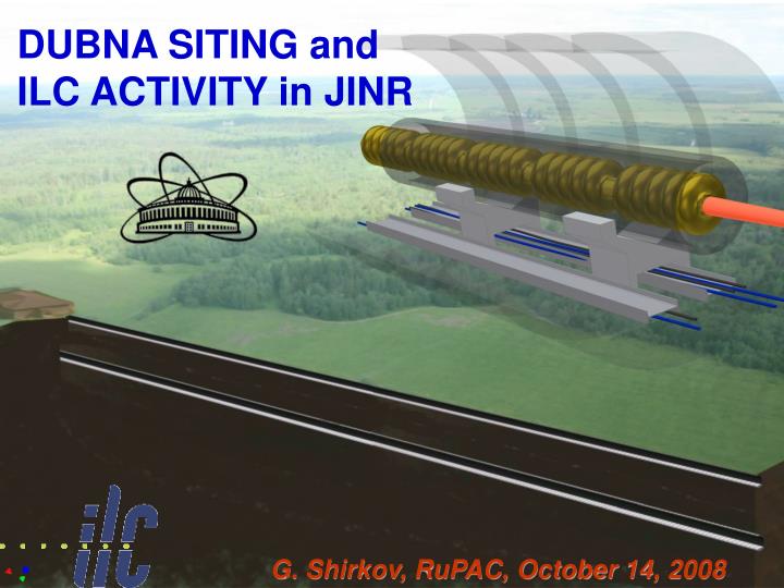
DUBNA SITING and ILC ACTIVITY in JINR. G. Shirkov, RuPAC, October 14, 2008. Main Linac Double Tunnel. Conventional Facilities. Three RF/cable penetrations every rf unit Safety crossovers every 500 m 34 kV power distribution.

E N D
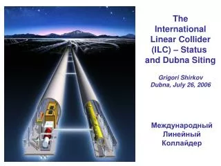
DUBNA SITING and ILC ACTIVITY in JINR G. Shirkov, RuPAC, October 14, 2008
Main Linac Double Tunnel Conventional Facilities • Three RF/cable penetrations every rf unit • Safety crossovers every 500 m • 34 kV power distribution • 72.5 km tunnels ~ 100-150 meters underground (for US, Asia, and CERN cites) • 13 major shafts > 9 meter diameter • 443 K cu. m. underground excavation: caverns, alcoves, halls • 92 surface “buildings”, 52.7 K sq. meters = 567 K sq-ft total
Value Estimate The value and explicit labor estimates are current as of 01.02.2007 The estimate contains three elements:
Documentation and Cost Estimation of Dubna Site July 2006 (for Vancouver GDE): JINR prepared and filled the necessary documents for possible ILC hosting to BCD (CFS chapter) – Site Assessment Matrix. • Official document from Russian State Project Institute (GSPI, Moscow) with estimations on: • Conventional facilities cost • Siting (tunnel, land acquisition) cost and time schedule • Energetic and power cost • Operational cost • Labor cost November 2006 (for Valencia GDE): JINR prepared and filled the necessary documents as a sample site for possible ILC hosting to RDR (Work Breakdown Structure - WBS). This document was also prepared with GSPI and submitted by Design Cost Board of GDE. Russian State Project Institute (GSPI, Moscow) – the most powerful and professional institute in Russia with 60 years history: design and construction of almost all Soviet and Russian Nuclear power stations, Nuclear centers (Sarov, etc), Scientific Nuclear accelerator centers (JINR Dubna, IHEP Protvino, ITEP Moscow, INR Troitsk, etc)
Layout of ILC in the Moscow Region Tver region Moscow region
This Workshop Working Groups Shallow solutions: Explore features and develop reduced-cost, shallow tunnel solutions. Both CLIC and ILC. Includes single tunnel. Infrastructure: Review infrastructure requirements and develop cost-effective solutions for accelerator infrastructure – power, water, air etc. Both CLIC and ILC. Siting: Examine possible sites and evaluate possible design differences that accommodate features. Includes staging, design modifications and upgrade issues. Accelerator Systems: particular focus on the central injection complex, BDS and RTML. Global Design Effort
Conclusions • We have presented the elements of the GDE plan for the next phase, which we call the Technical Design Phase. • A two stage ILC Technical Design Phase (TDP I 2010 and TDP II 2012 is proposed) • Overall Goals: Cost reduction, technical design and implementation plan on the time scale of LHC results • SCIENCE remains the key to ultimate success.
Unique Proposal of Tunnel Solution in Dubna Region The ILC is proposed to be placed in the drift clay at the depth of 20 m (at the mark of 100.00 m) with the idea that below the tunnel there should be impermeable soil preventing from the underlying groundwater inrush. It is possible to construct tunnels of the accelerating complex using tunnel shields with a simultaneous wall timbering by tubing or falsework concreting. Standard tunnel shields in the drift clay provide for daily speed of the drilling progress specified by the Project of the accelerator (it is needed approximately 2.5 years for the 50 km tunnel).
Dubna proposal: Shallow site with single tunnel buildings Vertical shaft Communication tunnel vertical communication shaft vertical shaft accelerator tunnel
A new suggested variant of the accelerator tunnel layout is under discussion and estimations now. It assumes the following: • main (beam) tunnel is located at approximately -20 m (at abs. level -100 m) in order to have impermeable layer above and below to be prevented from subsoil waters; • service (communication) tunnel is located directly above the main and around the earth surface (<-3-4 m), practically repeating the relief; • technological connection between two tunnels is provided with vertical shafts of different diameters, which are drilled with usual method; • connection between surface buildings and underground infrastructure is provided with vertical and horizontal shafts (elevators, stairs, etc) • cost of communication tunnel itself (without any equipment) is estimated by GSPI as about 20 Mrubbles (800 k$) per 100 m.
Service (communication) tunnel • Such a variant is more efficient economical by several reasons: • Service (communication) tunnel can have any size (section) for loading or filling the beam tunnel with any equipment, it is made by open-cut method; • Vertical connections are made by well-boring (relatively cheap method in comparison with case of horizontal ones), at the same time their number and sizes can be optimized. In addition – they do not require damp course; • Export of the drain waters is provided directly in accordance with relief, without any pumping stations; • Exploitation of the communication tunnels is sufficiently easier; • Cable and other technological connections between service tunnel with surface building is sufficiently reduced.
Advantages of the ILC construction in Dubna: • JINR as a basic scientific and organizational structure with international intergovernmental organization. • Prevalent legal practice makes it possible to get the land of the ILC location to permanent free use just as it has been done for JINR, according to the agreement between JINR and the RF government. • The proposed territory is extremely thinly populated and practically free of industrial structures, rivers and roads. • The area is absolutely steady seismically and has stable geological characteristics. • A flat relief and geological conditions allow to place ILC on a small depth (about 20 m) in the dry drift clayand to perform construction of tunnels, experimental halls and other underground objects with the least expenses, including cut-and-cover.
6. Sources of the electric power of sufficient capacity: transmission line of 500 kV, the Konakovo electric power station and the Udomlia atomic power plant. 7. The developed system of transport and communication services, good highways and railways, water-way (the Volga river basin); 8. Presence of a modern network and information infrastructure, including one of the largest center in Europe the “Dubna” Satellite Communication Center. 9. A special the economic zone in Dubna provides preferential terms for development and manufacture of high technology technical production. 10. A powerful scientific and technical potential of Dubna makes it possible to involve additionally specialists from world scientific centers into the international collective of highly-qualified scientific manpower. 11.The only one shallow tunnel with accelerator structures and communication gallery on the surface
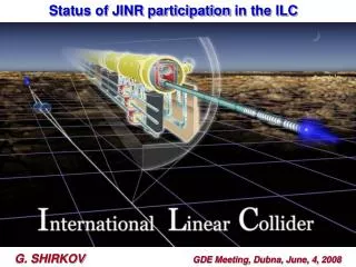
Participation of JINR in the ILC International Technical Activity International Linear Collider: accelerator physics and engineering • Theme leaders: A.N. Sissakian G.D. Shirkov • Period: 2007- 2009 • Preparation of works of JINR; • Participation in estimations • and design of ILC elements
JINR PARTICIPATION IN R&D OF ILC SUBSISTEMES AND IN RELATED PROJECTS 1. Construction of ILC photoinjector prototype. 2. The LINAC-800 based test-bench with electron beam 3. Development of power supply devices for RF system 4. Metrological laser complex 5. Development and design of cryogenic modules and test systems. 6. Preparation of technical base of cryogenic supply to test cryomodules of the 4th gen. 7. Calculation of electrical and magnetic fields 8. Engineering survey and design works 9. Development of the electron cooling method. LEPTA project. 10. Project CLIC 11. Project FLASH 12. Development of diagnostic systems; development of built-in devices. 13. Development of magnetic systems of the ILC damping rings 14. Development of diagnostics for large cryogenic systems. Personnel ~ 100 persons In total year 2007 ≈ 900 k$ (personnel 580 k$ + travels 90 k$ + R&D 230 k$)
Laser metrology JINR developed test bench at CERN for precise laser metrology. Results ofAug’06 0,5 micron precision of laser beam position measurement on the base of 40m is achieved. At JINR it is planned to set this complex at b.118 (base is 2x250m). DR magnetic system simulations and magnet prototype construction JINR in collaboration with SLAC works on design and possibility to construct at JINR workshop series of magnetic system elements of DR (few dipole magnets). It is also planned to provide test of those elements. This activity is performed in frames of MoU JINR-KEK on ATF collaboration. Similar MoU between JINR and SLAC is under assignment CLIC: Continuation of works with CERN: new prototype of the resonator was manufactured, proposed ways for increasing of the pulsed heating, results of the works on 2nd stage of the Contract approved by CERN. LINAC-800: Commissioning of the accelerating section (20-40 MeV) - 2008 Construction works at b.118, engineer infrustructure, modulator test bench, klystron test bench)
2004 2008 To the 1st FEL Injector : electron gun + chopper + pre-buncher. String test of the Sm-Co undulator magnetic field Linac-800
JINR Participation in the ILC Cryomodule design. This international effort includes contributions from many institutions, including JINR together with FSUE “RFNC-VNIIEF” (Sarov, Russia). The key participants at the JINR are J.Budagov, B.Sabirov and A.Sukhanova. In the recent months JINR and Sarov have started a collaboration with INFN-Pisa on a bi-metallic Ti-SS transition tube to connect the Titanium helium vessel with a 76-mm diameter two-phase helium line in an ILC cryomodule (CM). Such a transition would allow for a very substantial cost savings in the ILC cryomodule production. Successful preliminary tests with prototype transition tubes of a smaller diameter, supplied by JINR and Sarov, were conducted by JINR in collaboration with INFN-Pisa.
Test results create a great impression at ILC Meeting in Florence. In the future the collaborative R&D of bi-metallic tubes for the ILC cryomodule and testing them should be done in conformance with the Technical Specifications. For more statistic a total of twenty tubes will then be delivered to Fermilab for further integration into a cryomodule. JINR with Sarov will carry out the work for production 10-20 units of the bi-metallic tubes will be sent consequently to the INFN/Pisa and FNAL following the schedule parties will agree timely. The tubes will be used at FNAL and in Pisa for ILC purposes.
Photo injector prototype activity Main results in 2007: - JINR scientists worked in operation runs at PITZ and FLASH. Several scientific missions of JINR staff to DESY Hamburg and Zoethen were done. - JINR performed design and started constructionofthe test bench for CsTe photocathode preparation. This test bench is planed to be used for preparation of GaAs photocathode in future. - 8 publications in 2007: