Download

1 / 19
190 likes | 205 Views
State Machine Diagram. Chapter 10. State Machine Diagram. Used to describe system behavior. State Machines. Simple set of notational elements. trigger[guard]/activity. transition. Initial state (pseudo-state). Super state. Final state. state-name. State. Start/Final states.

E N D
State Machine Diagram Chapter 10
State Machine Diagram • Used to describe system behavior
State Machines • Simple set of notational elements trigger[guard]/activity transition Initial state (pseudo-state) Super state Final state state-name State
Start/Final states • Start state indicates where the state machine starts • Final state indicates that the machine should terminate
States • Intermediate state of the system • entry/activity: perform the activity when the state is entered • exit/activity: perform the activity when the state is exited • trigger/internal activity: perform the internal activity whenever trigger occurs state-name entry/activity exit/activity trigger/internal activity trigger/internal activity …
Activity state • Think of this as a state with a separate running thread that can be interrupted at any time • As opposed to being in a “regular” state just waiting for a trigger to arrive • Note that a trigger[guard]/activity (next slide) cannot be interrupted state-name do/activity
Super state • Just a way of grouping states to remove clutter from a diagram • When two or more states have the same transition[guard]/activity (next slide) to the same next state you can group them together and not have to show each and every individual transition x[y]/z x[y]/z x[y]/z
Concurrent states • When you have multiple state machines running concurrently (threads or multi-processing) • The history pseudo state (H) indicates the default state when entire machine is started H
Transition • Cause the current state of the machine to change from state to another • trigger: event that occurs causing the change • [guard]: condition that must be true for the change to occur • activity: action performed as a result of the transition trigger[guard]/activity
Transition • All three parts are optional • If there is no specified trigger, the state performs any enter/exit/internal activities then leaves immediately • Transitions out of a single state must be unique with respect to trigger[guard] specifications • Unless you want a stochastic system (randomly choose the transition when the trigger[guard] occurs) • Can use logical connectors (and, or, not)
Summary • Processing begins at initial state • Proceeds to intermediate states • Event triggered transition • Leave one state, enter the next • Unconditional transition • Processing in the state finishes (e.g. start state) • Concludes when the (a) final state is reached • May be more than 1 final states
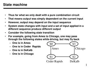
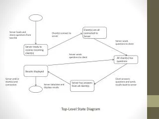
Example Login characters typed <cr> typed Enter Password Authenticate User invalid user valid user
State Machines (cont.) • Like everything else, state machines will be developed through a series of refinements • The process ends when all states are “self-explanatory” • The process results in a hierarchy of state machines • Root node of the hierarchy is the system itself
State Machines (cont.) • Note that these are NOT flow charts!!! • Flow charts provide a one-to-one correspondence with code • State machines provide a one-to-one correspondence with architectural elements
Scoring • Manual mode only • Score counter starts at 0 • Increments by 1 each time the ball hits the paddle • Stops incrementing when the ball moves below the paddle (game ends) • Should be displayed at all times
Difficulty levels • Manual mode only • When the number of paddle hits (score) is a multiple of 10 but not a multiple of 20, increase the speed of the ball by 5% • When the number of paddle hits (score) is a multiple of 20, decrease the size of the paddle by 5%
Score database • When a game ends (see scoring on previous slide) have the user enter their name and save the name/score in a “database” • Add a button to show the top 10 scores and the player names • Add a button to show all scores for a particular player (read the player name from the user)
Deliverables • Sequence diagram(s) • User interface design (mock-up) • State machine diagram for the user interface • Revised specification • Due two weeks from tonight • Be prepared to discuss next week