Download
1 / 23
230 likes | 403 Views
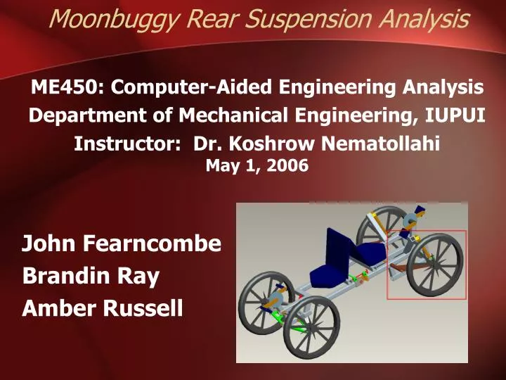
Moonbuggy Rear Suspension Analysis ME450: Computer-Aided Engineering Analysis Department of Mechanical Engineering, IUPUI Instructor: Dr. Koshrow Nematollahi May 1, 2006 John Fearncombe Brandin Ray Amber Russell. Objectives.

E N D
Moonbuggy Rear Suspension Analysis ME450: Computer-Aided Engineering Analysis Department of Mechanical Engineering, IUPUI Instructor: Dr. Koshrow Nematollahi May 1, 2006 John Fearncombe Brandin Ray Amber Russell
Objectives • Perform finite element analysis of moon buggy suspension using ANSYS Workbench • Evaluate stress and deformation resulting from applied load • Perform iterations as needed until a satisfactory design is realized
Introduction • Moon buggy originally designed in Spring 2005 by ME 462 design team • Lower a-arms on original suspension failed • Normal loading conditions were determined to be approximately 200 pounds-force • The initial design was modeled to determine if it could be modified and safely used
Theoretical Background • Utilized ten-node SOLID92 tetrahedral elements • Ideal for complicated solids with curved boundaries
Model Details for Existing Design • Originally modeled in Pro/Engineer (IGES), then imported into ANSYS Workbench • Static analysis only • Aluminum alloy construction • 200 pounds-force load applied at shock mount • Fixed supports at axes of rotation • Displacement constrained in transverse direction
Deformed Geometry for Existing Design • Maximum Deflection of 2.78×10⁻³ inches • Maximum deformation occurs near shock absorber mount
Principal Stresses for Existing Design • Maximum principal stress of 1.791 ksi • Yield stress for 6061 aluminum alloy is 35 ksi • Maximum stresses occur where the part failed
Shear Stress for Existing Design • Maximum shear stress of 1.421 ksi • Deemed insignificant • Failure due to fatigue in aluminum
Model Details for First Iteration • Modeled and constrained as before • Aluminum alloy construction • 200 pound-force load again applied at shock mount • Modeled as one-piece construction with no welds
Deformed Geometry for First Iteration • Maximum Deflection of 5.42×10⁻³ inches • Occurs below shock absorber mounting bolt
Principal Stresses for First Iteration • Maximum principal stress of 221.267 psi • Yield stress for 6061 aluminum alloy is 35 ksi • Maximum stresses occur near the shock absorber mounting bolt
Shear Stress for First Iteration • Maximum shear stress of 20.917 psi • Shear stress concentrated near welds • Quality of welds had been an issue
Model Details for Final Iteration • Modeled and constrained as before • Aluminum alloy construction with steel reinforcement plates at shock absorber mount • Two points of attachment to wheel hub housing to relieve stress on aluminum members
Deformed Geometry for Final Iteration • Maximum Deflection of .114×10-3 inches • Located at mid-section of shock absorber bolt
Principal Stresses for Final Iteration • Maximum principal stress of 1.875 ksi • Yield stress: • 6061 aluminum alloy is 35 ksi • 4140 steel is 45 ksi • Maximum stresses occur in the steel reinforcing plates
Shear Stress for Final Iteration • Maximum shear stress of 1.170 ksi • Located in steel reinforcing plates • Achieved objective of localizing stresses within steel elements
Impact Statement • Through the use of finite element analysis on the rear suspension of the moon buggy the vehicle has become more safe, stable, and easier to maintain. • By optimizing the design before production, we have alleviated costly and potentially dangerous failures.
Conclusion - Advantages of Final Iteration • Maximum stress is distributed on steel reinforcing plates • Ability to quickly and inexpensively replace the parts most likely to fail • Easier fabrication • No reliance on welds for structural stability
Bibliography • ME 450 Course Text • ANSYS Website www.ansys.com • Car Suspension and Handling. Bastow, Donald. London : Pentech Press ; Warrendale, Penn. : Society of Automotive Engineers, 1993. • Chassis design : principles and analysis Milliken, William F., 1911- • www.engineersedge.com – Material Properties