Download
1 / 15
1.37k likes | 3.24k Views
Basic electronics. Optical interfaces: Detect and control. Ohm’s law. Current = voltage / resistance I = V / R V = I x R Definitions Voltage = potential energy / unit charge, units = Volts Current = charge flow rate, units = Amps Resistance = friction, units = Ohms Example

E N D
Basic electronics Optical interfaces: Detect and control
Ohm’s law Current = voltage / resistance • I = V / R • V = I x R Definitions • Voltage = potential energy / unit charge, units = Volts • Current = charge flow rate, units = Amps • Resistance = friction, units = Ohms Example • Voltage drop when current flows through resistor • V1 - V2 = I R V1 I R V2
+ + Schematics • Symbols represent circuit elements • Lines are wires Battery Sample circuit V I R Resistor Ground Ground voltage defined = 0
R1 V I + + R2 Note: these points are connected together I V R2 R1 I1 I2 Parallel and series resistors Series circuit V = R1 I + R2 I = Reff I Reff = R1 + R2 Series • same current flows through all Parallel • save voltage across all Parallel circuit I = V/R1 + V/R2 = V/Reff 1/Reff = 1/R1 + 1/R2
+ I Vin Vout R1 R2 I Resistive voltage divider • Series resistor circuit • Reduce input voltage to desired level • Advantages: • simple and accurate • complex circuit can use single voltage source • Disadvantage: • dissipates power • easy to overload • need Rload << R2 Resistive divider I = Vin/Reff = Vout/R2 Vout = Vin (R2 / (R1 + R2) ) New schematic symbol: external connection
+ Variable voltage divider • Use potentiometer (= variable resistor) • Most common: constant output resistance Variable voltage divider Vout = Vin (Rout / (Rvar + Rout) ) New schematic symbol: potentiometer I Vout Vin Rvar Rout I
Capacitor charging curve time constant = RC Vin + Vout t = RC I Vout t R V Q C New schematic symbol: capacitor Capacitors • Charge = voltage x capacitance • Q = C V Definitions • Charge = integrated current flow , units = Coloumbs = Amp - seconds • I = dQ/dt • Capacitance = storage capacity, units = Farads Example • Capacitor charging circuit • Time constant = RC = t Capacitor charging circuit V = VR + VC = R dQ/dt + Q/C dQ/dt + Q/RC = V/R Q = C V (1 - exp(-t/RC)) Vout = Vin (1 - exp(-t/RC))
Resistive ac circuit V0 cos(2 pf t) R I = (V0/R) cos(2 pf t) New schematic symbol: AC voltage source AC circuits • Replace battery with sine (cosine) wave source • V = V0 cos(2 pf t) Definitions • Frequency f = cosine wave frequency, units = Hertz Examples • Resistor response: I = (V0/R) cos(2 pf t) • Capacitor response: Q = CV0 cos(2 pf t) • I = - 2 pf CV0 sin(2 pf t) • Current depends on frequency • negative sine wave replaces cosine wave • - 90 degree phase shift = lag • Capacitive ac circuit • 90 degree phase lag V0 cos(2 pf t) C I = - 2 pf CV0 sin(2 pf t)
Simplified notation: ac-circuits • V = V0 cos(2 pf t) = V0 [exp(2 p j f t) + c.c.]/2 • Drop c.c. part and factor of 1/2 • V = V0 exp(2 p j f t) Revisit resistive and capacitive circuits • Resistor response: I = (V0/R) exp(2 p j f t) = V / R = V/ ZR • Capacitor response: I = 2 p j f CV0 exp(2 p j f t) = (2 p j f C) V = V/ ZC Definition: Impedance, Z = effective resistance, units Ohms • Capacitor impedance ZC = 1 / (2 p jf C) • Resistor impedance ZR = R Impedance makes it look like Ohms law applies to capacitive circuits also • Capacitor response I = V / ZC
Explore capacitor circuits Impedance ZC = 1/ (2 p jf C) • Limit of low frequency f ~ 0 • ZC --> infinity • Capacitor is open circuit at low frequency • Limit of low frequency f ~ infinity • ZC --> 0 • Capacitor is short circuit at low frequency Capacitive ac circuit V0 cos(2 pf t) C I = V/ZC
Capacitor charging circuit = Low-pass filter I Vout Vin =V0 cos(2 pf t) R I C Revisit capacitor charging circuit Replace C with impedance ZC • Charging circuit looks like voltage divider • Vout = Vin (ZC / (ZR + ZC) ) = Vin / (1 + 2 p jf R C ) Low-pass filter Crossover when f = 1 / 2 p R C = 1 / 2 p t , t is time constant • lower frequencies Vout ~ Vin = pass band • higher frequencies Vout ~ Vin / (2 p jf R C ) = attenuated • Low-pass filter response • time constant = RC = t logVin Single-pole rolloff 6 dB/octave = 10 dB/decade knee log(Vout) f = 1 / 2 p t log(f )
I Vin =V0 cos(2 pf t) R L I New schematic symbol: Inductor Inductors • Voltage = rate of voltage change x inductance • V = L dI/dt Definitions • Inductance L = resistance to current change, units = Henrys Impedance of inductor: ZL = (2 p jf L) • Low frequency = short circuit • High frequency = open circuit Inductors rarely used Capacitor charging circuit = Low-pass filter High-pass filter response logVin Vout log(Vout) f = R / 2 p jL log(f )
Low-pass filter High-pass filter I I Vin =V0 cos(2 pf t) Vin =V0 cos(2 pf t) Vout Vout R C R C I I Gain response logVin knee log(Vout) Gain response f = 1 / 2 p t logVin Phase response Phase response log(f ) log(f ) log(f ) phase log(Vout) phase -90 degrees -90 degrees f = 1 / 2 p t f = 1 / 2 p t f = 1 / 2 p t log(f ) Capacitor filters circuits • Can make both low and high pass filters 0 degrees 0 degrees
Potentiometer AC voltage source - + Potentiometer 2-inputs plus center tap External connection Battery Op amp + Diode Capacitor Resistor Non-connecting wires Ground Inductor Summary of schematic symbols
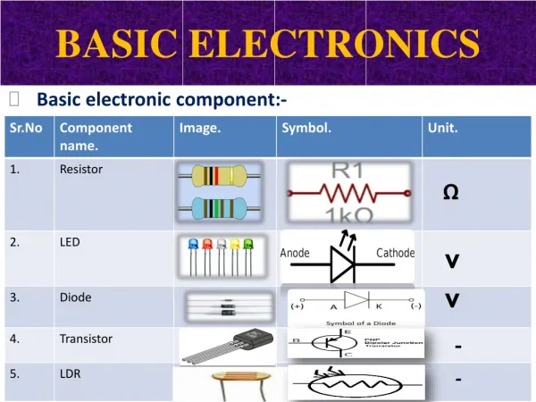
Color code Color black brown red orange yellow green blue violet gray white Number 0 1 2 3 4 5 6 7 8 9 • Resistor values determined by color • Three main bands • 1st = 1st digit • 2nd = 2nd digit • 3rd = # of trailing zeros • Examples • red, brown, black • 2 1 no zeros = 21 Ohms • yellow, brown, green • 4 1 5 = 4.1 Mohm • purple, gray, orange • 7 8 3 = 78 kOhms • Capacitors can have 3 numbers • use like three colors