Download
1 / 41
460 likes | 729 Views
Photonic Crystals in Integrated Optics: the Bumpy Way towards Optical Circuits. Acknowledgements. Semiconductor Device Physics Group The Boss: - Prof. Marc Ilegems My Supervisor: - Dr. Romuald Houdré

E N D
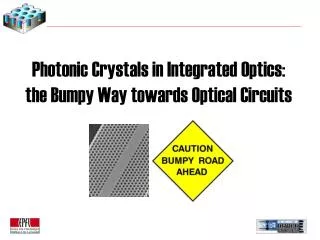
Photonic Crystals in Integrated Optics: the Bumpy Way towards Optical Circuits
Acknowledgements Semiconductor Device Physics Group The Boss: - Prof. Marc Ilegems My Supervisor: - Dr. Romuald Houdré Group members: - Dr. Rolando Ferrini - Dr. Andrea Dunbar - Benoît Lombardet - Barbara Wild
Outline of the Talk 1. Introduction What is a Photonic Crystal (PhC) Two-Dimensional PhCs –The System under Study 2. Experimental & Modeling tools Sample fabrication The different modeling tools (PWE, FDTD) The Internal Light Source Technique 3. Building blocks Straight waveguides Directional Couplers Coupled Cavity Waveguides 4. Photonic Crystals today and tomorrow 5. Conclusion
What is a Photonic Crystal ? Electron Photon • Electrons Crystal • Photons Low-loss periodic dielectric medium with high index contrast • Periodic refractive index • Periodic crystal potential • band structure w(k) • band structure w(k) • Electronicband gap • Photonic band gaps (PBGs) • Genuine bound states exist • Light can be localized at defects • due to multiple scattering (interference)
10 Bragg pairs in air (nhigh=3.48, nlow=variable) Normal incidence case wavelength The Bragg Mirror – A Basic PhC Generalization of the Bragg mirror
2D 1D 3D The Photonic Crystal Zoo
Two-Dimensional Photonic Crystals Purely 2D: Deep-etched Macroporous silicon a = 1.5 mm h = 100 mm …or low vertical refractive index contrast e.g. GaAs or InP. High vertical refractive index contrast, e.g. membranes 2D with vertical confinement:
Direct lattice Reciprocal lattice B.Z. Polarization Band structure (f = 0.3, e = 11.4) Gap map The Triangular Lattice Filling factor = Shole / Scell Reduced units: u = a / l q =ka / 2p
Photonic Crystals for Integrated Optics The main application area for PhCs is integrated Optics • Use of the bandgap to provide high reflectivity • mirrors for waveguiding, cavities, … • Use the strong dispersion available in PhCs (dispersion engineering). • Advantages: • Wavelength scale control of light propagation • Intrinsically lossless bends • High integration density / Cascadability • One step fabrication • New functionalities
Outline of the Talk 1. Introduction What is a Photonic Crystal (PhC) Two-Dimensional PhCs –The System under Study 2. Experimental & Modeling tools Sample fabrication The different modeling tools (PWE, FDTD) The Internal Light Source Technique 3. Building blocks Straight waveguides Directional Couplers Coupled Cavity Waveguides 4. Photonic Crystals today and tomorrow 5. Conclusion
Lithographic tuning: • l is fixed and a is changed • The band gap is explored as a function of reduced frequency u=a/l Scaling property The Internal Light Source Technique: Lithographic Tuning The transmission through a simple slab is given by T = I1(l) / I0 (l)
The Internal Light Source Technique: The Heterostructure Internal source of spontaneous emission (QWs or QDs) GaAs GaAs / AlGaAs multilayer structure + 3 layers of self-organised InAs QDs • Quantum dots: • broad spectrum “white light” • low light reabsorption • emission wavelength 1050 nm • Spectral width guided signal 150 nm
The Internal Light Source Technique: The Three Signals D. Labilloy et al., Phys. Rev. Lett. 79, pp. 4147, (1997) H. Benisty et al., IEEE J. Lightwave Technol. 17, pp. 2063 (1999) R. Ferrini et al., IEEE J. Quantum Electron. 38, (7), pp. 786, (2002).
The Internal Light Source Technique: The Setup R. Ferrini et al., IEEE J. Quantum Electron. 38, (7), pp. 786, (2002).
Towards Camera Towards Spectro Sample Position The Internal Light Source Technique
Exp. fit Basic Characterization GaAs • Gap position • Transmission in • the gap • Filling factor Quantitative results ! • T (4 rows) • R (4 rows) • Quality factor • Cavity order Airy-fit
Outline of the Talk 1. Introduction What is a Photonic Crystal (PhC) Two-Dimensional PhCs –The System under Study 2. Experimental & Modeling tools Sample fabrication The different modeling tools (PWE, FDTD) The Internal Light Source Technique 3. Building blocks Straight waveguides Directional Couplers Coupled Cavity Waveguides 4. Photonic Crystals today and tomorrow 5. Conclusion
Straight Waveguides W3 GaAs Transmission dip due to the Mini-Stop Band (MSB) (1) S. Olivier et al., Phys. Rev. B, 63, pp. 113311, (2001)
U=0.24 U=0.2475 U=0.253 Visualization of the MSB by FDTD
Design B Design C Directional Coupler: Sample Layout GaAs Three different lengths: 100 a, 200 a, 400 a Sample fabricated by University of Würzburg
Raw spectra Spectra normalized with W3 Coupling length Directional Coupler: Experimental Coupling Length W3 design B Scan over u Design B: Lc = 350 9 a 80 mm Design C: Lc = 290 175 a
Directional Coupler: Supermode Approach Supermode Approach: Rabi oscillation of 2 coupled oscillators:
Fundamental mode Lc 700 a Factor of 2 ! Experiment : Lc 350 a Cross-check by FDTD: Design B Ri / R0 = 0.8 Directional Coupler: Theoretical Coupling Length Cross-check by PWE: Dispersion of coupler (design B) confirms theoretical Lc D. Leuenberger, et al., Appl. Phys. Lett., to be published (2005)
Exp. B Exp. C Directional Coupler: Influence of the Barrier Holes • Conclusion • Coupling length depends on structural parameters, e.g. filling factor. • Coupling length depends sensitively on the radius Ri of the barrier holes. • The theoretical and experimental coupling length can be brought in agreement • with a ratio Ri/R0 of 0.8 for design B and 1 for design C. • In practice post-fabrication tuning may be necessary.
Coupled Cavity Waveguides: Motivation CCW = Coupled Cavity Waveguide • Motivation to study CCWs • Potential for efficient waveguides and bends. • Interesting dispersion properties, e.g. slow group velocity. • Potential for various building blocks, e.g. splitters, couplers and Mach-Zehnder interferometer. • Motivation to employ a Tight-binding formalism • The individual cavity modes form a natural basis for the description of CCWs. • The TB formalism describes the full dispersion properties with a handful parameters. • Potential to describe transmission in non-periodic chains of cavities in a recursive way.
The photons in a perfectly periodic PhC are not localized ( bound state). Coupled Cavity Waveguides: Analogy Electron - Photon Photon Electron • Electrons are localized in the vicinity of the individual atoms ( bound state). • Electrons can be trapped in asingle quantum well ( bound state). • Photons can be localized in a defect cavity due to multiple scattering ( bound state). • Single QWs can be arranged to form a superlattice. • Single cavities can be arranged to form a CCW.
Coupled Cavity Waveguides: Bandformation Two coupled cavities: Single cavity: Three coupled cavities: Example: H1-cavity The coupling of an infinite chain of cavities creates a mini band. Supports 2 degenerate modes Leads to 4 eigenstates Leads to 6 eigenstates
Coupled Cavity Waveguides: Tight Binding Approach (1) • Formalism supports degenerate multi-mode case. • The TB coefficients are explicitly calculated from the single cavity field distribution.
Coupled Cavity Waveguides: Tight Binding Approach (2) In the case of multi-mode cavities the TB parameters E, R, S and T are matrices. The dispersion relation is given by the generalized eigenvalue Eq.: Single mode case:
PWE TB Coupled Cavity Waveguides: Dispersion Relations H1-M CCW (1 row sep.): H1-M CCW (3 rows sep.):
Coupled Cavity Waveguides: Dispersion Relations E2-M CCW (3 rows sep.):
Coupled Cavity Waveguides: Conclusion • The TB approach: • provides and accurate description of the CCW dispersion, especially for cavity separations 3 rows. • can tackle CCWs based on multimode cavities. • is an ab-initio approach which does not involve any free fitting parameters. • has been cross-checked by the PWE method. D. Leuenberger, et al., J. Appl. Phys. 95 (3), 806-809 (2004)
Outline of the Talk 1. Introduction What is a Photonic Crystal (PhC) Two-Dimensional PhCs –The System under Study 2. Experimental & Modeling tools Sample fabrication The different modeling tools (PWE, FDTD) The Internal Light Source Technique 3. Building blocks Straight waveguides Directional Couplers Coupled Cavity Waveguides 4. Photonic Crystals today and tomorrow 5. Conclusion
Photonic Crystals Today High Q cavity in membrane structure (Q=45’000, V=7.0 x 1014 cm3) Y. Akahane et al., Nature 425, p.944, (2003) Low loss single line defect up to 1 cm in length (Propagation loss 0.76 dB/mm) Y. Sugimoto et al., Optics Express 12, p. 1090, (2004) Electrically injected tunable laser S. Mahnkopf, IEEE Phot. Techn. Lett. 16, p.729, (2004) Channel drop filter (0.12nm resolution @ 1.55mm H. Takano et al., Appl. Phys. Lett., 84, (13), p. 2226, (2004)
BUT: All-PhC integrated optical circuit Photonic Crystals Tomorrow • Tuning and switching: • Strain tuning • Optical pumping of nonlinear materials • Free-carrier injection • Temperature tuning • Infiltration with liquid crystals • Propagation effects: • Superprism • Self collimation • Lensing • Negative refraction • Polarization Control Tuning of high Q-microcavity for WDM applications
Photonic Crystals become Industrial Reality Photeon Technologie (http://www.photeon.com) From blaze photonics (http://www.blazephotonics.com) December 2003: Pirelli releases Tunable laser without moving parts Based on PhC technology
Conclusions • The ILS technique provides quantitative transmission spectra for a wide range of different structures. • PhC-based linear couplers are a feasible alternative for switching of light. The coupling lengths are in the order of 80 mm, which is rather large for PhC-based circuits but still small compared to conventional integrated Optics. • Coupled cavity waveguides are an interesting concept for various building blocks, such as waveguides, bends and splitters. • The TB approach provides an accurate description of the CCW dispersion with a handful of parameters. The approach has been successfully validated by the PWE method.