Download

1 / 22
230 likes | 375 Views
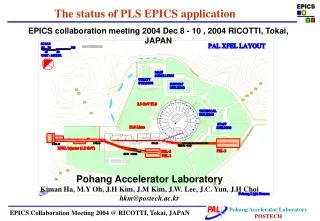
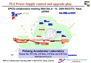
Slow Global Orbit Feedback at Pohang Light Source (PLS). Heung-Sik Kang Pohang Accelerator Laboratory Pohang, Korea. Aerial View of PAL. Brief History of PLS. Project started Apr. 1 1988 Ground-breaking Apr. 1 1991 2-GeV Linac commissioned Jun. 30 1994

E N D
Slow Global Orbit Feedback at Pohang Light Source (PLS) Heung-Sik Kang Pohang Accelerator Laboratory Pohang, Korea
Aerial View of PAL Brief History of PLS • Project started Apr. 1 1988 • Ground-breaking Apr. 1 1991 • 2-GeV Linac commissioned Jun. 30 1994 • Storage ring commissioned Dec. 24 1994 • User’s service started Sept. 1 1995 • Energy ramping to 2.5 GeV Sept. 1 2000 • 2.5-GeV injection Nov. 1 2002
Pohang Light Source 2.5 GeV Linac / Storage Ring • Beam Energy 2.5GeV • Beam Current 200mA • Lattice TBA • Superperiods 12 • Circumference 280 m • Emittance 18.9 nm-rad • Tune 14.28 / 8.18 • RF Frequency 500 MHz • Energy spread 8.5 x 10⁻⁴ PLS Orbit Stability Requirements <1% x-y coupling>
March 2004, w/o SOFB For 9 days Orbit Feedback • Slow global orbit feedback (SOFB) • Improvement of Power Supplies • V: 12 bit -> 20 bit resolution (22 ea) New power supply with the controller developed in BESSY II • H: 12 bit -> 16 bit (22 ea) modification of existing power supplies • Operational since October 2004 • Feedback Speed: 4 sec • SVD algorithm, MATLAB / EPICS • Feedforward correction for ID is under test • Fast global orbit feedback (FOFB) • Under consideration RMS-y 200 m Frequency Spectrum of BPM reading High frequency movement
MATLAB GUI for Slow Global Orbit Feedback • The orbit feedback algorithm uses the SVD (singular value decomposition) method. • Use the Matlab Channel Access to EPICS IOC of BPMs and correctors • The GUI displays the response matrix, the spectrum of singular values, the real time orbit, and the correction kick.
P 6 P 7 P 5 P 8 P 4 P 9 P 3 P 1 P 2 C4 C5 ID C3 C6 C1 C2 Correctors and BPMs for SOFB • 9 BPMs & 6 Correctors /sector Totally, 108 BPMs and 70 correctors in each plane • BPM electronics: Bergoz MUX BPM • Insertion Devices (6) • Undulator: U7, EPU6, U10, In-Vacuum Revolver (min. gap: 5 mm) • Multipole Wiggler: HFMX, HFMS One sector • SOFB uses • - 2 correctors (C1 & C2) / sector -> 22 correctors in each plane • - 6 BPMs / sector • - Current dependence table for BPM electronics Horizontal plane: 16 bit resolution -> 0.06 rad/ 1 bit Vertical plane: 20 bit resolution -> 0.004 rad/ 1 bit
Orbit Variations in SOFB during USER RUN(Nov. 16 – 25, 2004) For 10 days Reference orbit is re-set For one day RMS-y RMS-x RF freq • Reference orbit is re-set at 150 mA after refill. • Current dependence data of BPM electronics is referenced to the BPM reading at 150mA 1. The number of correctors is not enough for correction 2. To effectively compensate the BPM electronics’ current dependence
180 mA 2 m 120 mA False BPM Reading BPM reading Beam current • BPM Reading 1) Real Beam Position change 2) BPM Electronics’ dependence on Ambient temperature 3) BPM Electronics’ dependence on Beam current 4) Chamber movement • Current Dependence table is used to subtract the false value from the BPM reading for SOFB • But, chamber movement is not compensated. - BPM electronics problem: Gain drifts and non-linearities • Compensation of false BPM reading is absolutely necessary in order to minimize the false motion by orbit feedback. • Ambient temperature dependence can not be compensated, thus should be minimized.
Beam Current Dependence of BPM electronics Horizontal vertical Linear rate of current dependence [um/mA] 188 mA 153 mA 112 mA • Non-linearity of current dependence • Different Change rate of current dependence • low current rage: 153 – 112 mA (blue line) • high current range: 188 – 153 mA (green line) • Current Dependence table for SOFB : red line (188-112mA) BPM reading change between 120mA and 180mA (not include the bad BPMs) X – rms : 2.9 m Y – rms : 5.0 m
BPM 9-2Y BPM 7-5 Y BPM 9-5Y 12-8Y BPM 6-4Y 5 m 10 m 2 m Patterns of BPM’s Intensity dependence Chamber Motion + BPM electronics Temperature of Vacuum Chamber in straight section ( Sep. 14 – 15, 2004, Bad Orbit condition) After the orbit correction
BPM Chamber Movement Photon Stop BM Photon Fan One sector • vacuum chamber moves due to the change of synchrotron radiation heat load • dependent on orbit • Look-up table is not easy to implement.
9-5 Y BPM 9-5Y Change of BPM Reading in SOFB BPM with a negligible chamber movement BPM with a small chamber movement 7-6 Y Beam current 7-5 Y 5 m 5 m BPM with a large chamber movement SOFB ON SOFB OFF 9-5 Y 1 m 5 m
BPM Chamber Movement 4-7 4-6 4-5 4-8 4-4 4-9 4-3 5-1 4-2 BPM 40 m 10 m y 5-1 40 m 4-9 10 m 10 m 10 m 4-8 10 m 4 m 4-7 x 4 m 2 m 4-6 Measurement of BPM Chamber Movement sector number Digital Position sensor (accuracy: < 100 nm) Beam Current @ 2.5 GeV 200mA
3CV1 2CV1 9CV2 3CV2 4CV2 Variations of Corrector Currents in SOFB Beam current • Very similar to BPM chamber movement • BPM electronics' current dependence looks compensated well.
BPM 7-4Y 2 m 18:00 Dec. 6 2 hours Ambient Temperature Dependence of BPM Electronics(BPM reading oscillation) BPM 8-2Y 5 m Cooling Fan OFF AGC • The same oscillation was observed in the ambient air temperature in the control shed where the BPM electronics is. • BPM electronics Must be influenced by the ambient temperature. • One BPM electronics module shows Dependence on Ambient temperature : 1.4 m / C • Ambient temperature in control shed should be well controlled. 0.02 V
BPM’s intensity Dependence limits the SOFB performance. Solution is TOP-UP! BUT, Decided not to use it until …. Because 1. For Linac, Injection efficiency is not so good compared to Booster. Synchronization of RF between SR and Linac is required. 2. We will start SASE-FEL project in 2005. No. 1 Priority of Linac is changed…
PAL XFEL Project Period: 2005-2009 Budget: 80 M$
QM How to Compensate Chamber Motion in SOFB • Real-time measurement of BPM Chamber Motion for all BPMs (108 ea) by Digital position sensor or LVDT (Budget allocated in 2005) • Chamber position is monitored with respect to Girder, which is equivalent to Quad because Girder is very rigid. • EPICS Database • Compensate the chamber motion from BPM reading in SOFB (data refresh time : 1-3 minutes) • Neglect the Girder motion with respect to ground, and the Girder to Girder differences • Quad does not move as the Beam loading changes. • Care about the orbit with respect to Quad. Chamber QM invar
FB OFF FB ON BPM 4-3Y 2 m SOFB for Insertion Device Due to EPU gap change Beam current 13:41 • Vertical orbit changes up to 6 m in rms when the EPU gap is moving between 20 and 25 mm. • Feedforward correction is required. H: 16-bit correctors V: 20-bit correctors
Feedforward for EPU6 New Correctors for Feedforward PM2 PM6 PM3 PM4 PM5 PM1 PM7 PM8 PM9 Q4D BM1 SD Q4 Q5 SF Q6 BM2 BM3 Q5D Q1 Q2 Q3 Q6D CM6 Q1D CM4 Q3D SFD Q2D ID CM2 CM5 CM1 CM3 SDD Feed-forward correction - correctors: 1CM6 and 2CM3 just done for test New correctors for Feedforward ready for test - speed: 10 Hz
EPU6 Feed-forward Correction Feedforward table Vertical correctors: 1CM6 and 2CM3 5th degree polynomial for fitting Feedforward speed: 10 Hz
Summary • Achieved orbit stability by SOFB - short term (1 hour) : < 1 m - long term (12 hours) : < 3 m • BPM Chamber movement due to Synchrotron Radiation heating mainly limits the SOFB performance. Improvement Plan of SOFB in 2005 • Real-time measurement of BPM Chamber Motion for all BPMs (108 ea) • Reduction of BPM Noise • Feedback speed : 4 sec 2 sec • 70 correctors in vertical plane 20-bit resolution