Download

1 / 23
250 likes | 474 Views
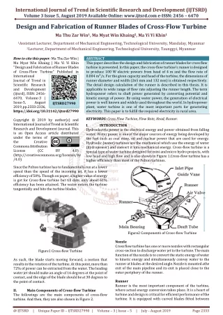
An Evaluation of Blockage Corrections for a Helical Cross-Flow Turbine. Robert J. Cavagnaro and Dr. Brian Polagye Northwest National Marine Renewable Energy Center (NNMREC) University of Washington. Oxford Tidal Energy Workshop April 7, 2014. Motivation.

E N D
An Evaluation of Blockage Corrections for a Helical Cross-Flow Turbine Robert J. Cavagnaro and Dr. Brian Polagye Northwest National Marine Renewable Energy Center (NNMREC) University of Washington Oxford Tidal Energy Workshop April 7, 2014
Motivation • NNMREC has developed a “micropower” turbine for providing power to co-located oceanographic equipment • Understand hydrodynamics of the full-scale turbine by testing at lab scale • Determine if corrections rectify variable turbine performance at different testing facilities Blockage Ratio • Lab-scale – high variability of performance with velocity and facility • Field-scale – limited variability of performance with velocity
Micropower Rotor Parameters • High-Solidity, Helical Cross-flow turbine • N: Number of blades (4) • H/D: Aspect Ratio (1.4) • φ: Blade helix angle (60o) • σ: Turbine solidity (0.3) • Hydrofoil:NACA-0018 • Lab (1/4) scale • H = 23.4 cm, D = 17.2 cm, c = 4.0 cm • Field Scale • H = 101.3 cm, D = 72.4 cm • c = 17.3 cm
Performance Characterization Experiments Tow vessel Tow line (~100 m) Skiff (w/ load bank) • Adjustable resistive load bank and power monitoring • Direct rotor torque measurement • Angular position measurement • Inflow and wake velocity measurement • Upstream & downstream Acoustic Doppler Velocimeters • Thrust measurement Skiff attachment Generator & gearbox Torque sensor & encoder Upstream ADV Rotor
Field Experiment Implementation Turbine Integration with Skiff Wake Characterization Experiment
Performance Characterization Experiments Load cell • Torque control with particle brake • Reaction torque measurement • Angular position measurement • Inflow velocity measurement • Upstream ADV • Thrust measurement UW Flume Scale support cage
Experimental Facilities Bamfield Flume UW Aero Flume Cross Section (m2) Cross Section (m2) Flow Speed (m/s) Flow speed (m/s) Reynolds Number Reynolds Number Blockage Ratio Blockage Ratio Froude number Froude number Turbulence Intensity Turbulence Intensity
Blockage Corrections • Corrections rely on various experimental parameters T
Blockage Corrections: Glauert (1933) • Becomes unstable for CT ≤ 1 T
Blockage Corrections: Pope & Harper (1966) “… for some unusual shape that needs to be tested in a tunnel, the authors suggest…” T
Blockage Corrections: Mikkelsen & Sørensen(2002) • Extension of Glauert’s derivation, constrained channel LMADT T
Blockage Corrections: Bahajet al. (2007) • Iterative solution of system of equations, incrementing U3/U2 • Assumes U1, ω, T are same in tunnel and open water T
Blockage Corrections: Werle (2010) • Constrained channel LMADT Also reached by Garrett & Cummins, 2007 and Houlsbyet al., 2008 T
Case 1: Lab to Field Comparison Same flow speed (1 m/s), different blockage Field Lab No thrust measurements for lab test case at 1 m/s
Case 2: Performance with Varying Blockage Same flow speed (0.7 m/s) at different facilities Pope & Harper Bahajet al. Werle
Case 3: Performance at Varying Speed Same blockage ratio and facility • Indicates strong dependence on Rec at low velocity Pope & Harper Bahajet al. Werle
Reynolds Number Effect Approximate Local Velocity Sheldahl, R. E. and Klimas, P. C., 1981, “Aerodynamic characteristics of seven airfoil sections through 180 degrees angle of attack for use in aerodynamic analysis of vertical axis wind turbines,” SAND80-2114, March 1981, Sandia National Laboratories, Albuquerque, New Mexico.
Angle of Attack Variation Angular Position Tip Speed Ratio
Significance of Dynamic Stall Range of α at position of maximum torque along each blade
Conclusions • Determining full-scale, unconfined hydrodynamics through use of a model may be challenging • All evaluated corrections reduced scatter of lab scale performance data • Thrust measurements may not be needed to apply a suitable blockage correction • No corrections account for full physics of problem • Family of performance curves at low speed likely due to performance at low Reynolds number and dynamic stall • Caution is needed when applying blockage corrections • Especially for cross-flow geometry
Acknowledgements • This material is based upon work supported by the Department of Energy under Award Number DE-FG36-08GO18179. • Funding for field-scale turbine fabrication and testing provided by the University of Washington Royalty Research Fund. • Fellowship support was provided by Dr. Roy Martin. • Two senior-level undergraduate Capstone Design teams fabricated the turbine blades and test rig. • Fiona Spencer at UW AA Department and Dr. Eric Clelland at Bamfield Marine Sciences Centre for support and use of their flumes. Robert Cavagnaro is supported by the Department of Energy (DOE) Office of Energy Efficiency and Renewable Energy (EERE) Postdoctoral Research Awards under the EERE Water Power Program administered by the Oak Ridge Institute for Science and Education (ORISE) for the DOE. ORISE is managed by Oak Ridge Associated Universities (ORAU) under DOE contract number DE-AC05-06OR23100. All opinions expressed in this presentation are the author's and do not necessarily reflect the policies and views of DOE, ORAU, or ORISE.
Blockage Corrections: Bahajet al. (2007) Linear Momentum Theory, Actuator Disk Model Where U1 is the water speed through the disk Solved iteratively by incrementing ratio of bypass flow velocity to wake velocity (U3/U2) Free-stream performance and λ derived from velocity correction Depends on inflow velocity, blockage ratio, and thrust Bahaj, a. S., Molland, a. F., Chaplin, J. R., & Batten, W. M. J. (2007). Power and thrust measurements of marine current turbines under various hydrodynamic flow conditions in a cavitation tunnel and a towing tank. Renewable Energy, 32(3), 407–426. doi:10.1016/j.renene.2006.01.012
Induction & Wake Flow direction