Download
1 / 1
10 likes | 135 Views
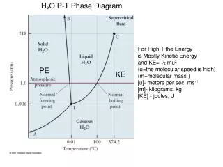
A High-Temperature CO 2 –Brine Phase-Partitioning Model for Application to Modeling CO 2 -Enhanced Geothermal Systems N. Spycher and K. Pruess Earth Sciences Division, Lawrence Berkeley National Laboratory, Berkeley, California. PHASE-PARTIONING MODEL. INTRODUCTION.

E N D
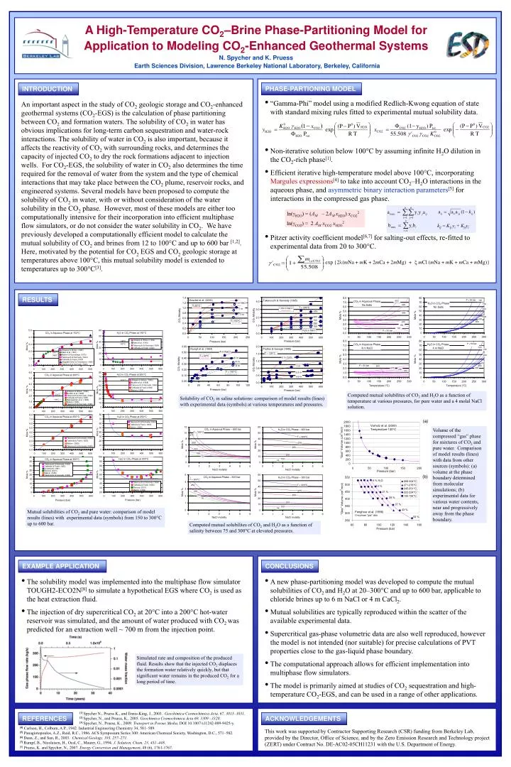
A High-Temperature CO2–Brine Phase-Partitioning Model for Application to Modeling CO2-Enhanced Geothermal Systems N. Spycher and K. Pruess Earth Sciences Division, Lawrence Berkeley National Laboratory, Berkeley, California PHASE-PARTIONING MODEL INTRODUCTION • “Gamma-Phi” model using a modified Redlich-Kwong equation of state with standard mixing rules fitted to experimental mutual solubility data. • Non-iterative solution below 100°C by assuming infinite H2O dilution in the CO2-rich phase[1]. • Efficient iterative high-temperature model above 100°C, incorporating Margules expressions[4] to take into account CO2–H2O interactions in the aqueous phase, and asymmetric binary interaction parameters[5] for interactions in the compressed gas phase. • Pitzer activity coefficient model[6,7] for salting-out effects, re-fitted to experimental data from 20 to 300°C. An important aspect in the study of CO2 geologic storage and CO2-enhanced geothermal systems (CO2-EGS) is the calculation of phase partitioning between CO2 and formation waters. The solubility of CO2 in water has obvious implications for long-term carbon sequestration and water-rock interactions. The solubility of water in CO2 is also important, because it affects the reactivity of CO2 with surrounding rocks, and determines the capacity of injected CO2 to dry the rock formations adjacent to injection wells. For CO2-EGS, the solubility of water in CO2 also determines the time required for the removal of water from the system and the type of chemical interactions that may take place between the CO2 plume, reservoir rocks, and engineered systems. Several models have been proposed to compute the solubility of CO2 in water, with or without consideration of the water solubility in the CO2 phase. However, most of these models are either too computationally intensive for their incorporation into efficient multiphase flow simulators, or do not consider the water solubility in CO2. We have previously developed a computationally efficient model to calculate the mutual solubility of CO2 and brines from 12 to 100°C and up to 600 bar [1,2]. Here, motivated by the potential for CO2 EGS and CO2 geologic storage at temperatures above 100°C, this mutual solubility model is extended to temperatures up to 300°C[3]. ln(gH2O) = (AM – 2AM xH2O) xCO22 ln(gCO2) = 2 AMxCO2xH2O2 RESULTS Computed mutual solubilites of CO2 and H2O as a function of temperature at various pressures, for pure water and a 4 molal NaCl solution. Solubility of CO2 in saline solutions: comparison of model results (lines) with experimental data (symbols) at various temperatures and pressures. (a) Volume of the compressed “gas” phase for mixtures of CO2 and pure water. Comparison of model results (lines) with data from other sources (symbols): (a) volume at the phase boundary determined from molecular simulations; (b) experimental data for various water contents, near and progressively away from the phase boundary. (b) Mutual solubilities of CO2 and pure water: comparison of model results (lines) with experimental data (symbols) from 150 to 300°C up to 600 bar. Computed mutual solubilites of CO2 and H2O as a function of salinity between 75 and 300°C at elevated pressures. EXAMPLE APPLICATION CONCLUSIONS • The solubility model was implemented into the multiphase flow simulator TOUGH2-ECO2N[8] to simulate a hypothetical EGS where CO2 is used as the heat extraction fluid. • The injection of dry supercritical CO2 at 20°C into a 200°C hot-water reservoir was simulated, and the amount of water produced with CO2 waspredicted for an extraction well ~ 700 m from the injection point. • A new phase-partitioning model was developed to compute the mutual solubilities of CO2 and H2O at 20–300°C and up to 600 bar, applicable to chloride brines up to 6 m NaCl or 4 m CaCl2. • Mutual solubilities are typically reproduced within the scatter of the available experimental data. • Supercritical gas-phase volumetric data are also well reproduced, however the model is not intended (nor suitable) for precise calculations of PVT properties close to the gas-liquid phase boundary. • The computational approach allows for efficient implementation into multiphase flow simulators. • The model is primarily aimed at studies of CO2 sequestration and high-temperature CO2-EGS, and can be used in a range of other applications. Simulated rate and composition of the produced fluid. Results show that the injected CO2 displaces the formation water relatively quickly, but that significant water remains in the produced CO2 for a long period of time. • [1] Spycher N., Pruess K., and Ennis-King, J., 2003. Geochimica Cosmochimica Acta, 67, 3015–3031. • [2] Spycher, N., and Pruess, K., 2005. Geochimica Cosmochimica Acta69,3309 –3320. • [3] Spycher, N., Pruess, K., 2009. Transport in Porous Media, DOI 10.1007/s11242-009-9425-y. • [4]Carlson, H., Colburn, A.P., 1942. Industrial Engineering Chemistry 34, 581–589. • [5] Panagiotopoulos, A.Z., Reid, R.C., 1986. ACS Symposium Series 300: American Chemical Society, Washington, D.C., 571–582. • [6] Duan, Z., and Sun, R., 2003. Chemical Geology, 193, 257–271. • [7] Rumpf, B., Nicolaisen, H., Ocal, C., Maurer, G., 1994. J. Solution. Chem. 23, 431–448. • [8]Pruess, K. and Spycher, N., 2007. Energy Conversion and Management, 48 (6), 1761-1767. REFERENCES ACKNOWLEDGEMENTS This work was supported by Contractor Supporting Research (CSR) funding from Berkeley Lab, provided by the Director, Office of Science, and by the Zero Emission Research and Technology project (ZERT) under Contract No. DE-AC02-05CH11231 with the U.S. Department of Energy.