Download
1 / 41
410 likes | 890 Views
2. Active and passive remote sensing. Passive: uses natural energy, either reflected sunlight or emitted thermal or microwave radiationActive: sensor creates its own energyTransmitted toward EarthInteracts with atmosphere and/or surfaceReflects back toward sensor (backscatter). 3. Widely used active remote sensing systems.

E N D
1. 1 ESM 266: Active microwave remote sensing Jeff Dozier
2. 2 Active and passive remote sensing Passive: uses natural energy, either reflected sunlight or emitted thermal or microwave radiation
Active: sensor creates its own energy
Transmitted toward Earth
Interacts with atmosphere and/or surface
Reflects back toward sensor (backscatter)
3. 3 Widely used active remote sensing systems Active microwave (radar)
long-wavelength microwaves (1-100cm)
recording the amount of energy back-scattered from the terrain
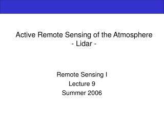
Lidar
short-wavelength laser light (e.g., 0.90 �m)
recording the light back-scattered from the terrain or atmosphere
Sonar
sound waves through a water column
recording the amount of energy back-scattered from the water column or the bottom
4. 4 Frequency-wavelength relation Generally in the microwave part of the spectrum we use frequency instead of wavelength
Typically measured in s�1, called Hertz (Hz)
Most often Gigahertz (GHz) = 109Hz
5. 5 Microwave band codes
6. Sending and receiving a pulse of microwave radiation
7. SIR-C/X-SAR images of Rondonia, Brazil
8. 8 Advantages of radar All weather, day or night
Some areas of Earth are persistently cloud covered
Penetrates clouds, vegetation, dry soil, dry snow
Sensitive to water content, surface roughness
Can measure waves in water
Sensitive to polarization and frequency
Interferometry (later) using 2 receiving antennas
9. 9 Disadvantages of radar Penetrates clouds, vegetation, dry soil, dry snow
Signal is integrated over a depth range and a variety of materials
Sensitive to water content, surface roughness
Small amounts of water affect signal
Hard to separate the volume response from the surface response
Sensitive to polarization and frequency
Many choices for instrument, expensive to cover range of possibilities
The math can be formidable
10. How it works Pulses of active microwave electromagnetic energy illuminate strips of the terrain at right angles (orthogonal) to the direction of travel
called the range or look direction
The terrain illuminated nearest the aircraft is the near-range
The farthest point of terrain illuminated is the far-range
11. How it works (cont.) Aircraft or satellite travels in a straight line: the azimuth direction
Pulses of microwave electromagnetic energy illuminate strips of the terrain orthogonal to direction of travel: the range or look direction
Terrain illuminated nearest the sensor in the line of sight is the near-range
The farthest point of terrain illuminated by the pulse of energy is the far-range
Generally, objects that trend (or strike) in a direction orthogonal (perpendicular) to the range or look direction are enhanced much more than those objects in the terrain that lie parallel to the look direction
Consequently, linear features that are imperceptible in a radar image using one look direction may appear bright in another radar image with a different look direction.
12. Nomenclature nadir
azimuth flight direction
look direction
range (near and far)
depression angle (?)
incidence angle (?)
altitude above-ground-level, H
polarization
13. Variability with look direction
14. Depression angles and incidence angles Depression angle (g): between a horizontal plane extending out from the sensor and the electromagnetic pulse of energy from the antenna to a specific point on the ground
Incidence angle (q): between the radar pulse and the normal to Earth�s surface
When surface is flat, q = 90��g
15. Polarization 1st letter is transmitted polarization, 2nd is received
Can have VV, HH (like)
HV, VH (cross)
16. Polarization with visible light In this case, incoming radiation (sunlight) is not polarized (or is polarized in both directions)
Vertically polarized light is reflected from surface
At this view angle, horizontally polarized light is not
So horizontal filter allows us to see the bottom
17. Polarization with radar
18. Radar geometry � is weird, not like cameras or multispectral sensors
Uncorrected radar imagery is displayed in slant-range geometry, based on the distance from the radar to each of the respective features in the scene
But can also display in ground-range geometry, so that features in the scene are in their proper planimetric (x,y) positions
Radar resolution has 2 dimensions, range and azimuth
20. Range resolution
21. Azimuth resolution
22. Foreshortening, layover, shadow
23. Foreshortening In flat terrain, easy to convert a slant-range radar image into a ground-range radar image
� but with trees, tall buildings, or mountains, you get radar relief displacement
the higher the object, the closer it is to the radar antenna, and therefore the sooner (in time) it is detected on the radar image
Terrain that slopes toward the radar will appear compressed or foreshortened compared to slopes away from the radar
24. Foreshortening
25. Layover Extreme case of foreshortening, when incidence angle is less than slope angle toward radar (i.e. ?<a)
cannot be corrected
got to be careful in the mountains
26. Shadow When slope away from radar is steeper than the depression angle, i.e. �a > ?
27. Speckle Grainy salt-and-pepper pattern in radar imagery
Caused by coherent nature of the radar wave, which causes random constructive and destructive interference, and hence random bright and dark areas in a radar image
Reduced by multiple looks
processing separate portions of an aperture and recombining these portions so that interference does not occur
28. Synthetic aperture radar (SAR) Major advance in radar remote sensing to improve azimuth resolution by synthesizing a long antenna
29. Synthetic aperture radar (SAR)
30. 30 Based on Doppler principle Frequency (pitch) of a wave changes if the receiver and/or source are in motion relative to one another
Train whistle has a increasing pitch as it approaches, highest when it is directly perpendicular to the listener (receiver)
Point of zero Doppler
After train passes by, its pitch will decrease in frequency in proportion to the distance it is from the listener (receiver)
This principle is applicable to all harmonic wave motion, including the microwaves used in radar systems
31. Synthetic aperture radar
32. Creation of SAR image
33. 33 Radar equation
34. 34 Radar backscatter coefficient Primary signal of interest
Percentage of electromagnetic energy reflected back to the radar from within a resolution cell
Depends on terrain parameters like
geometry, surface roughness, moisture content, and
radar system parameters (wavelength, depression angle, polarization, etc.)
35. Roughness
36. Nile River, Sudan
37. Sources of radar backscattering from a vegetation canopy Subscripts
t trunk
s soil
c leaves
m multiple
38. Types of scattering from a pine stand
39. Strength of scattering from a pine stand depends on frequency
40. RADARSAT-2 (launched Dec 2007) C-band radar (5.4 GHz) with HH, VV, HV, and VH polarizations
41. 41 SIR-C/X-SAR web site at JPL SIR-C
Spaceborne Imaging Radar-C (following SIR-A in 1981 and SIR-B in 1984)
X-SAR
X-band Synthetic Aperture Radar (built by Germans)
Flew on Shuttle, 2 10-day missions in 1994