Download
1 / 38
380 likes | 509 Views
Geometric and migrating characteristics of superimposed bedforms under oscillatory flows. By Yovanni Cataño And Marcelo H. García. Ven Te Chow Hydrosystems Laboratory Department of Civil and Environmental Engineering University of Illinois at Urbana-Champaign 2005. Outline.

E N D
Geometric and migrating characteristics of superimposed bedforms under oscillatory flows By Yovanni Cataño And Marcelo H. García Ven Te Chow Hydrosystems Laboratory Department of Civil and Environmental Engineering University of Illinois at Urbana-Champaign 2005
Outline • Acknowledgements • Motivation • Experimental setup • Formation of superposed bedforms under oscillatory flows • Main results: (a) Sandwaves (b) Ripples • Conclusions • Future work
Acknowledgements • Coastal Geosciences Program of the U.S. Office of Naval Research Grant: N00014-05-1-0083 • Prof. James Best University of Leeds (UK) • Prof. David Admiral University of Nebraska
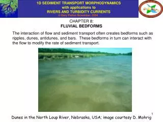
Motivation • Understanding formation and evolution of coexisting bedforms under combined flows • Important for the interaction of bedforms with coastal structures: pipelines, cables, cylinders, bridge piers, breakwaters… • Other applications include the exploitation of sands for construction purposes • Implications on effective roughness height induced by bedforms.
Experimental setup 1. wave flume; 2. wavemaker paddle; 3. injection of current; 4. wooden ramp; 5. waves; 6. Seatek sensors; 7. superimposed current; 8. sandy bed; 9. beach; 10. sediment trap; 11. movable carriage; 12. water surface acoustic sensor; 13. ADV probe.
Amalgamated bedforms Survey with the Seatek sensors Bed configuration with the presence of 2D and 3D ripples. Hydraulic conditions: Tw = 3.4 s, Hw = 10.7 cm, Lw = 7.7 m. Horizontal and transverse resolutions are 1 cm, and 4 cms, respectively.
Typical view of ripples superimposed on a sandwave under WA.
Results: sandwaves Measured dimensionless sandwave height as a function of the Reynolds wave number. Measured dimensionless sandwave length as a function of the Reynolds wave number.
harmonics Dimensionless sandwave length as a function of the Reynolds wave number Measured sandwave vertical growth rate as a function of the Reynolds wave number.
Vertical growth rate of sandwave as a function of time. Case of waves alone.
Measured dimensionless sandwave migration speed as a function of the Reynolds wave number.
Main findings:Sandwave formation and evolution Experiments for: 10 < ψwc < 88; 16000 < Rew < 500000, and 0.09 < θ < 0.54 For flat bed conditions • Sandwave geometry parameters such as height, length, and steepness show less scatter, although considerable, when plotted against Rew than for the case of ψwc or θ. • Both sandwave length and height decrease as the Reynolds wave number increases • Dimensionless sandwave migration speed increases as the Reynolds wave number increases. • Preliminary analysis suggest the existence of a simple relationship between the sandwave length (Lsw) and wavelength of the surface wave (Lw)
Results:Ripples superimposed to sandwaves Geometry Ripples over crest Dimensionless mean ripple wave length as a function of the Reynolds wave number defined as Rew = Uwca / ν. With ψwc Dimensionless mean ripple wave height as a function of the Reynolds wave number defined as Rew = Uwca / ν. With ψwc
Ripple speed Variation of ripple speed depending on its relative position over the sandwave under waves alone.
Larger asymmetry Smaller asymmetry Measured velocity profiles after 34 hrs. ΔX = 25.4 cm.
Mean value of measured dimensionless ripple speed as a function of the mobility number.
Main findings 10 < ψwc < 88 and 16000 < Rew < 500000, and 0.09 < θ < 0.54 For flat bed conditions • Ripples size, shape and speed vary depending on their relative position over the sandwave. • Measured ripple length and height show strong dependency on the Reynolds wave number Rew for WA and CF.
Thank you! Any questions?
Proposed experimental work (continuation) • Since the ripple washout mechanism continues to be unclear, it is proposed to reproduce higher values of the mobility number similar to those observed in the field. • Since bedforms are subjected to irregular flows in the field, it is easy to understand the urgent need to conduct laboratory experiments with the combination of irregular waves and currents. • Perform measurements of sediment concentration profiles along sandwave. • Signal Analysis of Time Series and Bottom Records • To explore convenience of using Hilbert and wavelet techniques along of FFT, and Spectral Analysis • Predictive tools • It is proposed to explore the use of analytical approaches, such as stability analysis and weakly non-linear theory, Mei theory.
Shortcomings & Recommendations • Use of linear small wave theory (Rigorously: Cnoidal, 2nd order Stoke’s theory) • Include in the calculations of θ the effect of form drag due to ripples and sandwaves. • Non-linearity due to beach reflection, and wavemaker? • So far, work with Uc < 20 cm/s • Due to a changing bed (Ripples and sandwaves), only mean velocity are suitable for description of global processes. • No turbulence characterization over ripples and sandwaves. • Better to use of PIV (Particle Image Velocimetry) or ADVP techniques (Acoustic Doppler Velocimeter Profiler)-> resolve turbulence, others….
Additional work would include: • To perform refined velocity measurements over an artificial fixed sandwave (If ADV is the only instrument available). • -Examine Reynolds stresses distribution and momentum fluxes over three and two dimensional ripples superimposed on sandwaves. - Estimation of the distribution of the friction factor fw, and roughness length zo, over the bedforms. - The implications for sediment transport characteristics would also be understood. - Will help future development of numerical and analytical models dealing with the morphodynamics of the studied bedforms. • With movable bed: The effects due to ripples and sandwaves must be separated to obtain a better description of the hydrodynamic processes over the whole flow field. ADV not suitable. It is better to use PIV (Particle Image Velocimetry) or ADVP (Acoustic Doppler Velocity Profiler) techniques where spatial and temporal resolution can be significantly improved. • Since bedforms are subjected to irregular flows in the field, it is easy to understand the urgent need to conduct laboratory experiments with the combination of irregular waves and currents.
References Cataño-Lopera, Y. and García, M.H., (2005e). “Geometry and Migration Characteristics of Bedforms under Waves and Currents: Part 1, Sandwave morphodynamics.” Submitted to Coastal Engineering. Cataño-Lopera, Y. and García, M.H., (2005f). “Geometry and Migration Characteristics of Bedforms under Waves and Currents: Part 2, Ripples Superimposed on Sandwaves.” Submitted to Coastal Engineering. Cataño-Lopera, Y. and García, M.H., (2005g). "Geometric and migrating Characteristics of Amalgamated Bedforms under Oscillatory Flows." Proceedings of the 4th IAHR Symposium on River, Coastal and Estuarine Morphodynamics, University of Illinois, October 4-7. Faraci, C. and Foti, E., (2002). “Geometry, migration and evolution of small-scale bedforms generated by regular and irregular waves.” Coastal Engineering, 47, 35-52. Williams, J.J., Bell , P.S. and Thorne, P.D., (2005). “Unifying large and small wave-generated ripples.” J. Geophys. Res., 110 (CO2008).
a d = fluid orbital diameter Reynolds wave number Shear velocity Go back Shields parameter Mobility number
Influence of development and migration of bedforms on the burial process Laser image of a sharp boundary between sand waves (top left corner) and smooth seafloor. Table 1. Ref. Reineck, H.-E, Singh, I.B., and Wunderlich, F., 1971. Table 2. Ref. Characteristics of offshore sand bedforms, Morelissen, R., et al. Coastal Engineering (2003), 197-209
Also….. Other contributors: ONR program: Theoretical and field: Gallagher et al. (1998) Theoretical and Laboratory: C. C. Mei, MIT (2002) Theoretical (Stability analysis), numerical modeling, and field of sandwaves: Amos, Németh, Komarova, Holsters, Gekerma, others....
Dimensionless ripple length as a function of the mobility number under waves alone and combined flow. Back
Dimensionless ripple height as a function of the mobility number under waves alone and combined flow. Back
Experimental Instrumentation ADV (SonTek) for 3D velocity profiles and sinking of the mine Back Back A 32 composite element array of sub-aquatic acoustic sensors (SeaTek - Multiple Transducer Arrays) for 3D mapping of the bottom Acoustic sensor (STI) for measurement of time series of water surface profile
Velocity profiles recorded after 34 hours. The duration of each velocity point was 180 s covering more than 60 wave periods. Vertical velocity profiles are spaced every 25.4 cm in the x-direction over the centerline of the flume. Hydraulic conditions: Tw = 4.1 s, Lw = 9.4 m, Hw = 10.4 cm, h = 56 cm under waves alone.
Velocity measurements Contour map of the sandy bottom and velocity vectors over the centerline of the center sandwave. Flow conditions for waves alone: Tw = 2.3 s, Lw = 4.9 m, Hw = 17.4 cm, h = 60 cm. Average values of morphodynamic characteristics, for ripples: length, lr = 12.7 cm, height, hr = 1.5 cm and speed, cr = 8.4 cm/day; for sandwave: length, lsw = 8.4 m, height, hsw = 40 cm and speed, csw = 95 m/year. Up to date only two experiments include this type of velocity measurements. back
Go back to theoretical background Go back to recommendations
Support Go back
Examples of surface profiles (case of waves alone) for: (Left) Quasi-sinusoidal wave type with Tw = 1.5 s, Lw = 3.0 m, Hw = 7.1 cm, Cw = 2.1 m/s, Stroke=6.1 cm. (Right) Stokes’ wave type with Tw = 2.9 s, Lw = 6.6 m, Hw = 8.7 cm, Cw = 2.1 m/s, Stroke=15.2 cm. Notice that η = 0 cm corresponds to the undisturbed water level of h = 56 cm
Theoretical, Németh et al. (2002) (agree with field data) …but not present study! Tm = (Time scale) ?? Ratio between measured data and predicted values as a function of the Reynolds wave number, Re: (a) Sandwave length, (b) Sandwave migration speed.