Download
1 / 30
300 likes | 414 Views
CONSTRUCTION OF COSMIC RAY DETECTORS CRD/ANALYSIS OF THE FAN OUT BOARD FOR THE QUARKNET PROJECT. Adenrele Fapohunda Engineering Department Electrical Engineering Benedict College. Supervisor: Thomas Jordan Educational Program Leader Fermi National Accelerator Laboratory. Contents.

E N D
CONSTRUCTION OF COSMIC RAY DETECTORS CRD/ANALYSIS OF THE FAN OUT BOARD FOR THE QUARKNET PROJECT Adenrele Fapohunda Engineering Department Electrical Engineering Benedict College. Supervisor: Thomas Jordan Educational Program Leader Fermi National Accelerator Laboratory
Contents Project Overview Introduction Project Description Board Technical Details Conclusion Acknowledgement References
Project Overview This presentation focuses on the construction of Cosmic Ray Detectors ( CRD) with a specific concentration on the Fan Out Board, which is a part of the whole set up of the CRD array. Working with the Education office, under the QuarkNet program, I and a team of other Interns, were responsible for assembling seventy-five CRDs, which were sent to High Schools, Colleges and Universities and were used to perform experiments. It should be noted that the construction of CRDs was a process carried out in the background whilst my research was specifically the analysis, replicating and troubleshooting of the GPS Fan-out board.
About Quarknet INTRODUCTION Quarknet is a teacher professional development sponsored by the NSF and DOE In Quarknet , teachers work on particle physics experiment during the summer and join a group of scientists and teachers working to introduce some aspect of their work in the classroom. The Quarknet department I worked with this summer made Cosmic Ray Detectors.
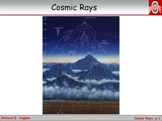
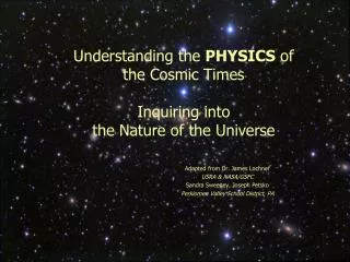
What are Cosmic Rays? They are radiation of energetic particles originating beyond the earth and impinge on the earth’s atmosphere. They are composed mainly of bare nuclei 87% protons, 12% alpha particles . The rest of it is made up of heavier atomic nuclei with their relative abundances comparable to those found in the sun. High energy neutrinos, electron and gamma rays make up a smaller part of it. Most cosmic rays are probably accelerated in the blast waves of supernova1 remnants [1]. They can travel from their distant sources to the earth because of their low matter density in space. 1 A rare celestial phenomenon involving the explosion of most of the material in a star, resulting in an extremely bright, short-lived object that emits vast amounts of energy. The death explosion of a massive star whose core has completely burned out.
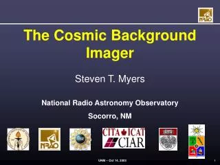
Fig 1. Crab Nebula1 taken by the Very Large Telescope Array Astronomy Picture of the Day - November 22, 1999 [2] 1 a diffuse mass of interstellar gas or dust or both.
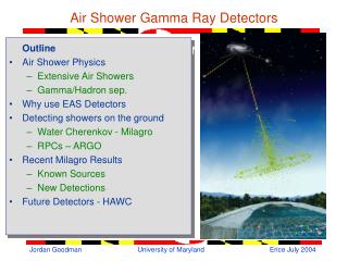
How does QuarkNet view showers? Fig 2. A Typical CRD setup
Fig 4. The QuarkNet Fan-Out Board RJ 45 slave DS9C0402M DS90C031BTM RJ45 to DAQ RJ45 to GPS antenna
Purpose /Use of the Quarknet Fan-Out Board PROJECT DESCRIPTION Merits of the Fan-Out Board • Reduces the problem of toting around individual GPS antenna to view cosmic showers • Allows various DAQ boards to listen/receive data from one particular GPS antennae Used to multiply and fan out a signal from 1 GPS antenna to several DAQ boards
On the QuarkNet Fan-Out Board, there are two major Integrated Circuits (ICs) whose functions cannot be underestimated and as a result I have analyzed them in this paper. They are: TECHNICAL DETAILS/BOARD COMPONENT FUNCTIONALITIES DS90C031BTM DS90C402M
DSC90C031BTM- Low Voltage Differential Signal Is a quad CMOS1 differential line driver designed for applications requiring ultra low power dissipation and high data rates. Designed to support data rates in excess of 155.5Mbps(77.7MHz) using LVDS technology Accepts TTL2/CMOS input levels and translates them to (350Mv) differential output Provides power-off high impedance LVDS outputs 1CMOS stands for Complementary-Symmetry/metal-oxide semiconductor. It a major class of Integrated Circuits. It includes Microprocessors , Static RAM and more 2TTL stands for Transistor-Transistor Logic. It is a class of Digital circuits built from Bipolar Junctions Transistor (BJT) and resistors. Used in music synthesizers, computer and more
DS90C402- Dual Low Voltage Differential Signaling( LVDS) Receiver It is a dual receiver device optimized for high data rate and low power applications It is a PCB space saving 8 lead small outline package The device goes along with the DSC90C401 and provides a pair speed solution for high speed point-to-point interface FEATURES Ultra Low Power Dissipation Operates above 155.5Mbps +/-100mV Receiver Sensitivity
Uses and Merits of LVDS Drivers LVDS Drivers and receivers are used primarily in an uncomplicated point-to-point configuration. They provides a clean signaling environment for the quick edge rates of the drivers.
Fig 7. Connection Diagram and Functional Diagram of DS90C402
RS-232 RS-232 is a standard for serial binary data interconnection between a DTE1 and a DCE2. It is commonly used in computer serial ports. Data is sent at a time-series of bits. Each circuit operates in one direction, that is, signaling back and forth between the DTE and DCE. The interface can operate in a duplex manner since transmit data and receive data are two separate circuits The steady state is referred to as the Marking state, while the start of a new character is referred to as Space state The digital ones and zeros transmit by switching between states and then back to start Marking state 1 DTE stands for Data Transmission Equipment 2DCE stands for Data Communcation Equipment
Voltage Levels Signals Operate between +/-3 to +/-15V Logic one is defined as a negative voltage, signal condition is Marking, and has the functional significance OFF. Logic zero is positive, signal condition is Spacing, and has functional significance ON. The standard specifies a maximum open-circuit of 25V, hence RS-232 compatible interface must be able withstand indefinite short to ground or to any voltage level up to 25V.
Common Data Transmission rates 50, 75, 110, 150, 300, 600, 1200, 2400, 4800, 9600, 19200, 38400, 76800 Interface Basics The maximum Data Transmission Rate( DTR) is 19.2K baud or bps even though slower rates are often used. Attempting to use baud rates over 19.2K could lead to noise being picked up especially over long cables. This could introduce data errors.
Conclusion I was able to assemble materials necessary to produce 75 Cosmic Ray Detectors ( CRDs). I got a more in depth knowledge about the Power Distribution Boxes. I succesfully replicated the QuarkNet Fan-out Board, trouble shoot it, and analyzed its component details.
I will like to thank: ACKNOWLEDGMENTS Almighty God, The Program Coordinators, Elliot McCrory, Dianne Engram My Supervisor, Thomas Jordan, Dr Davenport The QuarkNet Team, My Summer Colleagues, and last but not least, FERMILAB, for recruiting a wonderful and hardworking Intern. It has been nice!!
REFERENCES [1] NASA’s Goddard Flight Center, ( 2006, May), Introduction to Cosmic rays http://imagine.gsfc.nasa.gov/docs/science/know_l1/cosmic_rays.html [2] Brian Blosser, ( 2005,Aug) What are Galactic Cosmic Rays? cosray2.wustl.edu/tiger/science/GCRs/ [3] Digikey Corporation, (2003, September), Technical/Catalogue information on DS90C032B http://rocky.digikey.com/scripts/ProductInfo.dll?Site=US&V=14&M=DS90C032BTM [4] National Semiconductor, (2005 August), Technical/Catalogue information on DS90C402 http://www.national.com/ds/DS/DS90C402.pdf [5] Pinouts.ru team, ( 2005, March), RS-232 (EIA-232) serial interface pinout http://pinouts.ru/SerialPorts/RS232_pinout.shtml [6] Adrio Communications Ltd, an overview of RS232 Communication Standard http://www.radio-electronics.com/info/telecommunications_networks/networking/rs232/rs232.php
THE END Sorry!!! No Questions???