1 / 2

Figure 1 – Flight Computer Hardware Architecture

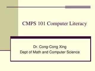
CAN bus. WiFi. flash memory. WiFi. pyro. GPS. IMU. ATV. APS. Flight Computer. Ground Station. Figure 1 – Flight Computer Hardware Architecture. flash memory. Log. Manager. F. F. F. WiFi out. WiFi in. Process. Hardware Driver. Muxer with named pipe input. F. Filtered

lunea-clark
Download Presentation

Figure 1 – Flight Computer Hardware Architecture

An Image/Link below is provided (as is) to download presentation Download Policy: Content on the Website is provided to you AS IS for your information and personal use and may not be sold / licensed / shared on other websites without getting consent from its author. Content is provided to you AS IS for your information and personal use only. Download presentation by click this link. While downloading, if for some reason you are not able to download a presentation, the publisher may have deleted the file from their server. During download, if you can't get a presentation, the file might be deleted by the publisher.

E N D

Presentation Transcript


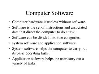
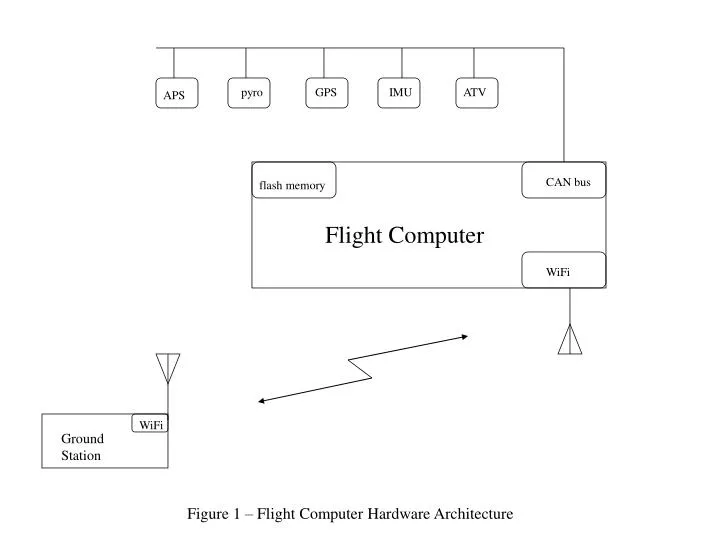
  1. CAN bus WiFi flash memory WiFi pyro GPS IMU ATV APS Flight Computer Ground Station Figure 1 – Flight Computer Hardware Architecture

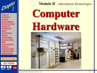
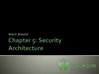
  2. flash memory Log Manager F F F WiFi out WiFi in Process Hardware Driver Muxer with named pipe input F Filtered output Logger CAN Reader FC2Net GPS IMU State Machine CAN bus F F IMU GPS SMART Sequencer Net2FC Legend CAN Writer Figure 2 – Flight Computer Software Architecture

More Related