Download
1 / 60
690 likes | 1.26k Views
TIMERS / COUNTERS. Two 16 bit timer/counters Can be programmed independently as – timer or event counter . Four-SFR’s connected with TIMER/COUNTER operation TMOD – Timer Mode Register TCON – Timer Control Register TH0, TL0 – Timer/Counter - 0 TH1, TL1 – Timer/Counter - 1

E N D
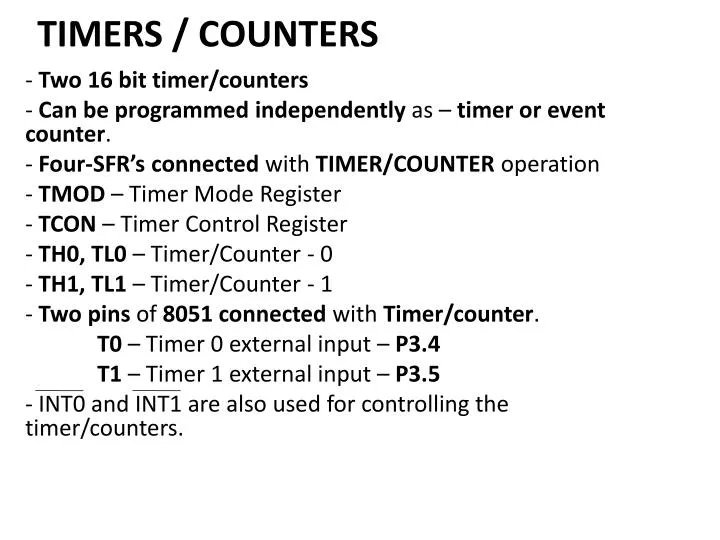
TIMERS / COUNTERS Two 16 bit timer/counters Can be programmed independently as – timer or event counter. Four-SFR’s connected with TIMER/COUNTER operation TMOD – Timer Mode Register TCON – Timer Control Register TH0, TL0 – Timer/Counter - 0 TH1, TL1 – Timer/Counter - 1 Two pins of 8051 connected with Timer/counter. T0 – Timer 0 external input – P3.4 T1 – Timer 1 external input – P3.5 - INT0 and INT1 are also used for controlling the timer/counters.
Timer Operation Timer Register (TH0, TL0 or TH1, TL1) incremented every m/c cycle. Thus working at increment frequency of 1/12 of oscillator frequency ( for 12 oscillator machine cycle ). Any preset value i.e. initial count can be loaded to TH0, TL0 or TH1, TL1. For Example – Clock frequency = 12 MHZ Clock period = 1/12 µ sec Machine cycle time = 1 µ sec Thus timer register will be incremented every microsecond. - If timer is initialized to 0000H Max. count = FFFFH max. time measured = 216 µ sec = 26 x 210 µ sec ≈ 26 millisecond ≈ 64 millisecond = 65.5 millisecond
Counter Operation • Counts pulses occurring at T0 pin (Timer/Counter 0) and/or T1 pin (Timer/counter 1). • May correspond to event like • Passing of railway coach from a point – axle counter • Rotation of speedometer cable – speedometer of vehicle • No. of persons visiting exhibition. • T0, T1 scanned every m/c cycle • nth m/c cycle – T1 or T0 = High • (n+1)th m/c – T1 or T0 = Low • Timer 0 or timer 1 incremented in (n+1)th m/c cycle • Count frequency = min 2 m/c cycle per count
In 12 MHz 8051 – m/c cycle = 1 µ sec • 8051 can count at the rate of 2 µ sec per count or higher • Any event when takes less than 2 µ sec may go unnoticed • C/T bit of TMOD selects Timer or counter operation for Timer 0 or Timer 1. • Timer/Counter operations are controlled by • Gate bit of TMOD • TR0 bit of TCON When Gate = 0 then TR0, TR1 act as Timer run control bits. 2 m/c cycle
Thus make Gate = 0 in TMOD By making TR0 (TCON. 4) or TR1 (TCON. 6) = 1 . through instruction, Timer/Counter 0 or Timer/Counter 1 may be started. • For starting and stopping the Timer/Counter from outside through hardware. • Make Gate = 1, TR0 = 1 through software. • By making INT0 or INT1 pin High will start Timer/Counter 0 or Timer/Counter 1 • Make INT0 or INT1Low to stop the Timer/Counter.
As value in Timer register rolls fromall ones (i.e. FFFFH) to all zero’s (i.e. 0000H) interrupt flag (TF0 or TF1) will be set. • TF0 (for Timer 0) and TF1 (for Timer 1) are bits of TCON SFR. • IF Timer 0 or Timer 1 interrupt is enabled then program control will branch to interrupt servicing routine.
Timer Register Interrupt TF0 Program Timer modes - 4 modes Mode 0 - 13 bit counter Mode 1 - 16 bit counter Mode 2 - 8 bit counter + auto reload Mode 3 - Split operation – Timer 0 Timer ISR RETI
Modes are set by M1 M0 bits of TMOD register. Mode 0 - 13 bit counter operation - TH0, TL0 (for Timer 0) or TH1, TL1 (for Timer 1) used as 13 bit counter. - All 8 bits of TL0 or TL1 - 5 lower bits of TH0 or TH1 are used, for counting. - When count rolls over from all 1’s to all 0’s, - interrupt flag TF0 or TF1 is set.
OSC ÷ 12 C/T = 0 TL0 (8 bits) TH0 (5 bits) TF0 Interrupt C/T = 1 Control T0 pin TR0 Gate INT0 pin Figure Timer 0, mode 0 - 13-bit counter
In above figure when C/T = 0 - timer operation count incremented every m/c cycle. provided TR0 (TCON. 4) or TR1 (TCON. 6) = 1 and Gate (TMOD. 3) or (TMOD. 7) = 0 Other way is- - TR0 or TR1 =1 - Gate = 1 and INT0 or INT1 = 1 - Thus by sending Logic High signal on INT0 (or INT1) pins Timer 0 or Timer 1 can be started.
- This can be used for finding pulse width in the following way. C/T = 0 – Timer operation TR0 or TR1 = 1 Gate = 1 Source of pulse connected to INT0 or INT1 pin • When pulse goes high timer starts counting at the rate 1/12 clock frequency • Which pulse goes low – Timer stops. INT0 or INT1 = Low - causes interrupt.
ISR can read the timer value. • ISR can store the timer value and process it as required by the application. Timer Starts Timer Stops Interrupt Generated +
OSC ÷ 12 C/T = 0 TL0 (8 bits) TH0 (8 bits) TF0 Interrupt Mode 1 – 16 bit counter C/T = 1 Control T0 pin TR0 Gate INT0 pin Figure Timer 0, mode 1 - 16-bit counter.
- Operation same as mode 0 except that all bits of TH0, TL0 or TH1, TL1 are used. When count rolls over from all 1’s to all 0’s – TF0 or TF1 interrupt flag is set. - Causes interrupt if enabled.
OSC ÷ 12 C/T = 0 TL0 (8 bits) TF0 Interrupt Mode 2 – 8 bit operation with auto reload C/T = 1 Control T0 pin TR0 Gate TH0 (8 bits) INT0 pin Figure Timer 0, mode 2 - autoreload.
Only TL0 or TL1 are used i.e. 8 bit counting. • Initial preset value is loaded to TH0 or TH1 by software. • The value is loaded to TL0 or TL1 by hardware automatically before starts of counting. • When count rolls from all 1’s (i.e. FFH) to all 0’s (i.e. 00H) • TF0 or TF1 flag is set • Preset value in TH0 or TH1 is reloaded to TL0 or TL1 • Operation i.e. Counting starts automatically.
OSC ÷ 12 Mode 3 – Split operation – Timer 0 C/T = 0 TL0 (8 bits) TF0 (1/12) fosc Interrupt C/T = 1 (1/12) fosc Control T0 pin TR0 Gate INT0 pin TH0 (8 bits) TF1 Figure Timer 0, mode 3-split to two 8-bit counters. Interrupt (1/12) fosc Control TR1
When Timer 0 is put in mode 3 • Acts as two 8 bit counters i.e. TL0 and TH0 become two separate counter. TL0 – 8 bit operation in mode 0 or mode 1 (Timer or Counter) controlled by C/T, TR0, Gate, INT0 – Sets TF0 when count rolls to all 0’s from all 1’s. TH0 – Timer function only. – Controlled by TR1 i.e. starts when TR1 = 1. When count rolls to all 0’s from all 1’s – TF1 flag is set.
Note – TR1 and TF1 are used in Timer 0 (TH0) even though they are bits for Timer 1. When Timer 1 is put in mode 3 – It just holds the preset count – same as TR0 = 0 i.e. opening the switch. [Modes 0, 1 and 2 are mostly used]
Timer Mode Control Register - TMOD Timer 1 Timer 0 Bit no. Symbol M1 and M0 specify the mode as follows:
If C/T = 1, the timers function as counters to count the negative transitions at T0 or T1 pins. If C/T = 0, the timers function as timers, that is, they basically count the number of machine cycles. Gate = 0 means that the timer is controlled by TR1 or TR0 only, irrespective of INT0 or INT1. Gate = 1 means that the timer control will depend on INT0 or INT1 and also on TR0 or TR1 bits
When data is written it gets latched. TMOD is used for setting mode bits M1, M0, Gate bit and C/T for Timer 0 and Timer 1. Bit 0 to 3 for Timer 0. Bit 4 to 7 for Timer 1.
Timer Control Register - TCON Bit 0 to 3 – used for interrupt functions Bit 4 to 7 – used for setting TR0, TR1 by software • Setting TF0, TF1 by counter i.e. hardware When count rolls from all 1’s to all 0’s.
Bit no. Symbol
Timer 0 Example – a. Configuring Timer/Counter using TMOD Timer 1
TIMER 1 - TIMER Mode = 00 (13 bit operation) TIMER 0 - Counter Mode = 01 (16 bit operation) TR0 TR1 C/T = 0 M1 M0 = 00 Gate = 0 C/T = 1 M1 M0 = 01 Gate = 0 TMOD = 0 0 0 0 0 1 0 1 = 0 5 H MOV TMOD, #05H
b. To load initial count as preset value • Work out the preset value = ABCDH • Load the preset value MOV TL0, #CDH MOV TH0, #ABH MOV TL1, #CDH MOV TH1, #ABH Timer 0 Timer 1
c. Start Timer/Counter through TR0, TR1 TCON = Interrupt Make TR0 = 1, TR1 = 1 TCON = 0 1 0 1 0 0 0 0 = 5 0 H MOV TCON, #50H or SETB TCON.4 SETB TCON.6 Timer
d. When count value in Timer Register transits from all 1’s to all 0’s • Following tasks need to be done. • Preset value to be loaded to Timer Register • Timer interrupt flag (TF0 or TF1) to be cleared • For continuous operation of Timer/Counter • Time clock • Pulse train generation etc.
- Can be achieved in 2 ways: 1. - Check Timer interrupt flag in loop. JNB TCON.5, $ or JNB TCON.7, $ • When interrupt flag is set then clear the flag. CLR TCON.5 or CLR TCON.7 • Load the preset count and restart SJMP to b
2. Write ISR for Timer 0 or Timer 1 and store at location 000BH (for Timer 0) or 001BH (for Timer 1) - Enable Timer 0 or Timer 1 interrupt by making bits ET0 (IE.1) or ET1(IE.3) = 1. SETB IE.1 or SETB IE.3 - When TF0 or TF1 is set - Interrupt will occur and program will branch to ISR location (000BH for Timer 0) or (001BH for Timer 1).
Step d will be different for different applications. • ISR • clear flag TF0 or TF1 • load preset value • Restart timer/counter RETI Example -1 - Generate a square wave of 50% duty cycle at pin p1.7. Use Timer 1 to generate time delay. Clock frequency = 12 MHz, 12 oscillator clock. Pulse width = 50 millisecond. - Let us work out the initial preset value.
50 ms 50 ms 1 m/c cycle = 1 microsecond 50 millisecond = 50 x 103 microsecond = 50, 000 m/c cycle FFFF = 65535 Difference = 65535 - 50000 = 15535 m/c cycle - Since count will roll from FFFF to 0000 additional m/c cycle will be required to set TF0 or TF1 .
Thus initial count must be 15536 i.e. = 30EEH By putting initial preset count of 30EEH (or 15536 decimal), the register will reach FFFF in 49999 m/c cycle and roll over to 0000 in 50,000th m/c cycle accounting for 50 millisecond
a. Configure Timer 1 = 1 0 H Gate = 0, C/T = 0, Mode = 01 (16 bit operator) MOV TMOD , # 1 0 H Make P1.7 = Low initially CLR P1.7 b. Load Preset Value KK : MOV TL1, #EEH MOV TH1, #30H
c. Complement P1.7 CPL P1.7 d. Start Timer 1 (TR1 = 1) SETB TCON.6 e. Check for TF1=1 in loop JNB TCON.7, $ f. TF1=1, Make TF1=0 CLR TCON.7 g. Stop Timer 1 Make TR1=0 CLR TCON.6 h. SJMP KK To reload preset valueComplement P1.7 Start Timer 1.
Steps d to g can be written as subroutine. Modified Program MOV TMOD, #10H CLR P1.7 • MOV TL1, #EEH MOV TH1, #30H CPL P1.7 ACALL TDELY SJMP KK
TDELY: SETB TCON.6 JNB TCON.7, $ CLR TCON.7 CLR TCON.6 RET
Example -2 • Generate a square wave of ON time of 3 ms and OFF time of 2 ms on P1.0. Clock frequency = 16 MHz, 12 clock m/c cycle • 16 MHz Frequency using Timer 1. 1 clock period = 1/16 µ sec
1 m/c cycle = 12/16 µ sec = ¾ µ sec 1 ms = 1000 µ sec = 4000/3 m/c cycle ≈ 1333 m/c cycle • 2 ms ≈ 2666 m/c cycle. Accounting for additional m/c cycle – 2665 • 3 ms ≈ 4000 m/c cycle. Accounting for additional m/c cycle – 3999
Count can be very well represented in 13 bits. Thus 13 bit operation i.e. Mode = 00 is O.K. • To calculate preset count max. no. in 13 bits(0-12) = 213 – 1 = 8191 for 2 ms delay – 8191 – 2665 = 5526 =158DH for 3 ms delay – 8191 – 3999 = 4192 = 1060H ; Configure Timer 1 MOV TMOD, #00H TMOD = = 00H
; Load preset value for 3 ms KK : MOV TL1, #60H MOV TH1, #10H ; Make P1.0 = High SETB P1.0 ; Start Timer 1 SETB TCON.6 ; Check for TF1 in loop JNB TCON.7, $ ; Make P1.0 = Low CLR P1.0
; TF1 = 1, Make TF1 = 0 CLR TCON.7 ; Stop Timer 1, Take TR1 = 0 CLR TCON.6 ; Repeat for 2 ms. . . . . . SJMP KK. MOV TL1, #80H MOV TH1, #15H SETB TCON.6 JNB TCON.7, $
Example – 8051 with clock frequency = 18 MHz • Generate a square wave of frequency 2 KHz on pin P1.0 using mode 2. • Calculate the smallest frequency possible without using software counter. Clock frequency = 18 MHz Clock period = 1/18 µ sec. 1 m/c cycle = 12/18 µ sec = 2/3 µ sec.
2 KHz square wave clock period = ½ 10-3 sec. = 0.5 millisecond Up time = 0.25 ms Dn time = 0.25 ms Up time = 0.25 ms = 0.25 x 10³ µ sec No. of m/c cycles in up time = (¼ x 103)/(2/3) = ¼ x 103 x 3/2 = 3/8 x 103 = 3000/8 = (30 x 25)/2 = 15 x 25 = 375 <- - - - - - 0.5 ms - - - - ->
Delay of 375 m/c cycle can be achieved in many ways. 375/3 = 125 – Generate delay of 125 m/c cycle 3 times 375/5 = 75 – Generate delay of 75 m/c cycle 5 times 375/15 = 25 – Generate delay of 25 m/c cycle 15 times : : : We can take any of the options. Let us take 1st one.
To generate delay of 125 m/c cycle Preset = (FFH) 255 – 125 = 130 Accounting of additional m/c cycle Preset = 131 = 83H ; Configure TMOD. Let us use Timer 0 MOV TMOD, #02H TMOD = = 02H
; Set P1.0 = High SETB P1.0 ; Load preset count MOV TH0, #83H ; Declare software counter ;Loop: MOV R3, 03H ; Start Timer
KK: SETB TCON.4 ; Check TF0 in loop JNB TCON.5, $ ; Stop timer by making TR0=0 CLR TCON.4 ; Clear TF0 Flag CLR TCON.5 ; Decrement and Branch to start timer. DJNZ R3, KK. ; Delay of 375 m/c cycle completed. CPL P1.0 SJMP Loop.
b. – Frequency is smallest when clock period = maximum i.e. Up time and Down time = maximum i.e. Delay is maximum. Delay is maximum when preset value =0 i.e. No. of m/c cycles in Up time = FF+1 No. of m/c cycles in Dn time = FF+1 Up time = 256 x 2/3 µ sec = 512/3 ≈ 170 µ sec Clock period = 341 µ sec. Frequency = 1/341 MHz = 1000/341 KHz = 2.92 KHz