Download
1 / 32
320 likes | 425 Views
3 rd Beaune conference New developments in photodetection. S tudy of Multi Anodes Photomultipliers for the PreShower read out of the LHCb experiment. Olivier Deschamps On behalf of the LPC CLERMONT-FERRAND LHCb group. LHCb. The L arge H adron C ollider b eauty experiment.

E N D
3rd Beaune conference New developments in photodetection Study of Multi Anodes Photomultipliers for the PreShower read out of the LHCb experiment Olivier Deschamps On behalf of the LPC CLERMONT-FERRAND LHCb group MAPMT Study
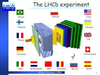
LHCb The Large Hadron Collider beauty experiment High energy Physics detector aiming at understanding the origin of the matter/anti-matter asymmetries in the universe. 20 meters long spectrometer on the Large Hadron Collider at CERN First data expected for 2007 Efficient trigger able to cope with the 40 MHz LHC beam frequency ThePreShower is of major importance for the first trigger level MAPMT Study
The LHCb PreShower One centimeter thick lead sheet as radiator in front of a 6000 cells scintillator wall. About hundred 64-Anodes PMTs perform the Read Out of the 6000channels. • Cells are grouped by block of 64, forming a preshower module. • Scintillation light is extracted from the plastic cells with 1mm thick helicoidalWavelength Shifting Fibres. • Both WLS fibres ends are connected to long clear fibres. • Each cell is read out through one channeof a 64-Anodes PMT. MAPMT Study
The PreShower Read Out 8x8 matrix of fibres connects the 64 preshower channels to the 64 Anodes of a PhotoMultiplier Tube ASIC specially designed Perfect 40MHz integrator more details in the poster session I H7546 from Hamamatsu A test bench has been developed for the MultiAnode PMT studies MAPMT Study
Outline • Purposes of the test bench • Description of the experimental setup • Protocol – stability checks • Results : • linearity measurements • gain measurements • anode uniformity measurements • cross-talk features • Conclusions and perspectives MAPMT Study
Purposes Of The Test Bench FEATURES ADRESSED IN THIS TALK • Linearity: The PreShower has to detect Minimim Ionizing Particles (20-30 photoelectrons) and to measure electromagnetic shower energy deposit (up to 100 MIPs) A 10 bits dynamics is required for PreShower. The photomultiplier response required to be linear over the whole range • Anode uniformity of the response: Same supply voltage for the 64 channels. The gains must (will) be adjusted by dedicated load resistors on the very front-end card. However non-uniformity must be in the larger ratio (1:3). • Uniformity of the response within one channel: this information may serve the adequate design of the connectic geometry fibre/PMT. • Cross-talk between the PMT channels: a large signal on one channel should not induce fake signal for adjacent channels. The cross-talk must be of the order of 1 % MAPMT Study
Experimental Setup - Global Sketch MAPMT Study
Studied MultiAnodes PMT µ-LENS OPTICAL QUARTZ FIBRE 3 mm OPTICAL COUPLER BALL LENS MonoAnode PMT as reference LED FILTER 2.5 cm Experimental Setup – the Light Sytem (1) Light signal shape Test Bench Signal (5ns Diode Voltage Pulse) PreShower signal from cosmics mimics the PreShower signal satisfactorily MAPMT Study
Experimental Setup – the Light Sytem (2) Fibre Active Core 200 µm THE LIGHT SYSTEM DESIGN MAPMT Study
Experimental Setup – the Light Sytem (3) CHARACTERISTICS OF THE FILTER Linear in optical density up to D=3 D = log (1/T) Light attenuation up to a factor 103 • The filter displacement is motorised The step resolution is about 20 µm. • 90 % of the dynamics is covered in 1/3 of the whole distance. • A lot of points are available at very small light yield. MAPMT Study
Experimental Setup – PM Support System DESIGN OF THE PM TABLE The PMT moveswith respect to the optical fibre position thanks to a x/y-translation-motorised table . The step resolution is again about 20 µm. Meant to allow fine structure tests of PMT window. MAPMT Study
Experimental Setup – Monitoring and Acquisition • MONITORING BY LABVIEW: • PM HV Supply • PM displacements in (x,y) • Optical filter displacements • HAND MONITORING : • The diode voltage • The pedestal mode • READ OUT: • 12 bits CHARGE ADC Lecroy • Acquisition Monitored With Labview MEASUREMENTS : Result from the mean and sigma of gaussian fit to the charge distribution from the PM response. Number of photo-electrons as MAPMT Study
Protocol stability checks • Light yield stability Reference monoanode PMT R5900 Atlas-Tilecal-like is used • The light is found stable within ± 1% • Thenumber of photon-electrons is gaussianly distributed with sigma at 6% • Pedestal stability • Pedestal spread is found to be around one ADC channel. • Stable along the operation time within 0.1 ADC channels • Stable with High Voltage variations within 0.2 ADC channels. • Optical coupling stability The light spot size on the filter is 3mm wide and logarithmically distributed Two reference monoanode PMTs are used to chec the coupling ratio stability • Stable within few per mil for 90% of the dynamics. Linearity measurements with a reference PMT possible in this range MAPMT Study
RESULTS (1) – the Linearity METHOD : make vary the attenuation – 50 measurements. Suppose the PMT is linear in the region of very high attenuations; fit of a straigth line to the response and compute the deviation to the expected linearity. MAPMT Study
RESULTS (1) – the Linearity CONVERSION CHARGE-CURRENT : suppose a triangular signal shape and measure the time half width. MAPMT Study
RESULTS (1)– the Linearity • CONCLUSIONS : • There are several ways to express the linearity of the PMT response. • The MA64 PMT is linear (within 5%) up to 100 photoelectrons at 850 V. • The MA64 PMT is linear (within 5%) up to 2000 photoelectrons at 650 V (expected working voltage). • Convenient way to compare with the electronics board design : a deviation to the linearity at the 5 % level is observed for a maximal current at the anode of about 1 mA. • Covers satisfactorily the whole dynamics range. MAPMT Study
RESULTS (1) – the Linearity Reference PM Channel 1 fired EFFECT OF THE SATURATION OF ONE CHANNEL ON THE OTHERS METHOD : Make use of the optical Cross-Talk between channels. Fibre is 1mm far from the PM window No effect of a saturating channel on others. SATURATION IS A LOCAL PHENOMENON MAPMT Study
RESULTS (2) – the Gain Measurement • METHOD : make vary the supply voltage of the PMT by step of 25V Nice fit of the power law Q=aVb for the PM64 up to HV = 900V (limit of a linear response). MAPMT Study
RESULTS (3) – the anode uniformity • METHOD : • measure the geometry of the PM window Fibre displacements of 200µm steps (by-product : the uniformity of the PM response within one channel). • The pixels are set regularly • similar answer between pixels • double structure; dissymmetry x/y (this image of the PMT window is consistent with the physical view) FIBRE CONNECTION • border effects dissymmetric (negligible in x, huge in y) FIBRE CONNECTION MAPMT Study
RESULTS (3) – the anode uniformity As an illustration of the test bench facility, gain uniformity measurements for the 64 channels of the Flat Panel PMT from HAMAMATSU studied in LPC from the purpose of medical imaging • Dispersion less than a factor 3 12 channels of the M64 APMT MAPMT Study
RESULTS (3) –anode uniformity within a pixel • METHOD : displace the PMT by step of 100 µm and measure the response. FIBER AT 200 µm FROM PMT WINDOW FIBER AT 1000 µm FROM PMT WINDOW Evidence of a double structure - intuitively dictated by the first look at the PM window - but strongly dissymetric. When the fibre is moved back, light is averaged and there is a useful surface large in X, thin in Y. MAPMT Study
RESULTS (3) – the anode uniformity • CONCLUSIONS • The measured pixels are set regularly • The maximum of the PMT answer is dissymmetric in x and y may serve the design of the FIBRE CONNECTION • There are border effects again dissymmetric may serve the design of the FIBRE CONNECTION • Variation from one channel to the other (less than 3) within the electronics gain correction requirements so far. • Non-uniformities occur in the multiplication chain MAPMT Study
RESULTS (4) – Cross-Talk • METHOD : • the fibre is 100µm far from the PM window • fire a central pixel and measure the 8 neighbours charge • result is normalised to the central value • two channels measured Basically NO INTRINSIC CROSS-TALK between the PMT channels MAPMT Study
Conclusions • the MultiAnodes PMT test bench is in successful operation • First results addressed: • gain measurements • anode uniformity measurements • linearity measurements • cross-talk features • MA64 PMT corresponds so far to the PreShower requirements MAPMT Study
Perspectives • Perform short and long term stability tests. In particular check the aging behaviour that could be crucial in the concern of the LHCb hostile environment. • Test other candidates : • XP1700 (Photonis), • M16 et M64 (six dynode stages) HAMAMATSU • Multi-elements APD array • Perform the acquisition with the LHCb PreShower full electronics chain developped. More details in a dedicated poster : « ReadOut system for the LHCb PreShower », LPC/LHCb, Session I MAPMT Study
Acknowlegements MAPMT Study
Light yield variation (9 hours run) • The light is found stable within ± 1% Protocol test : light yield stability check Reference monoanode PMT R5900 Atlas-Tilecal-like are used Number Of Photoelectrons: • Gaussianly distributed 6% fluctuation MAPMT Study
Protocol test :pedestal stability check METHOD : pedestal measurement from the diode trigger, varying the HV and the operation time. • Pedestal spread is found to be around or less than one ADC channel. • Pedestal mean value is stable along the operation time within 0.1 ADC channels • Pedestal mean value is stable with HV variation (500V to 900V) within 0.2 ADC channels. MAPMT Study
Protocol test :optical coupling stability 2 reference R5900 PMTs THE OPTICAL COUPLING The light spot size on the filter is 3mm wide. The filtered light is then dissymetric and logarithmically distributed. It is likely that the optical coupling is sensitive to the opening angle of the light from the fibre. If the initial spread is conserved, the coupling ratio R could be erratic. Significant effect is observed in the region of transition between full transparency and active part of the filter. Flat answer within few per mil for 90% of the dynamics. Linearity measurements with a reference PMT possible in this range. MAPMT Study
Results – The Linearity CROSS-CHECK : THE SHAPE DISTORTION IMAX = 0,8 mA 5% deviation MAPMT Study
Results – Anode Uniformity is the non-uniformity related to the photocathode or the multiplication system ? CONCLUSION : no correlation between Npe and the response. Also supported by the gain studies. MAPMT Study
Purposes Of The Test Bench (2) FEATURES NOT ADRESSED IN THIS TALK • Gain measurementsand calibration • Short and long term drift • Dark current • Measurements with few photo-electrons • Everything we did not think about yet MAPMT Study