Download
1 / 25
250 likes | 461 Views
Finite Element Model Generation. Model size Element class Element type, Number of dimensions, Size Plane stress & Plane strain Higher order elements Aspect ratio, Vertex angles, Degeneration Solution type Static: Max Stress, Crack propagation, Yield, Thermal

E N D
Finite Element Model Generation • Model size • Element class • Element type, Number of dimensions, Size • Plane stress & Plane strain • Higher order elements • Aspect ratio, Vertex angles, Degeneration • Solution type • Static: Max Stress, Crack propagation, Yield, Thermal • Dynamic: Natural Frequencies, Harmonic, PSD, Transient • Nonlinear: Stress stiffening, Buckling, Mass softening, Inelastic response, gaps, friction • Special Techniques: Super-elements, Cracks (1/4 points), Rubber
Model Sizing Strategy • Choose number of dimensions • Choose element type • Find element size • Estimate number of elements
Estimate Size • Computational time depends on development of stiffness matrix and solution of equations • Development of stiffness matrix and load vector is proportional to number of elements • Solution of simultaneous equations • Proportional to product of number of degrees of freedom and bandwidth squared • Number of degrees of freedom is number of nodes times number of displacements per node • Bandwidth is maximum node number difference times number of degrees of freedom across an element
Estimate Size (continued-2) • In linear problems solution of simultaneous equations dominates • In non-linear or transient problems the number of iterations and the solution algorithm can be proportional to number of degrees of freedom and computational time will be proportional to number of elements
Estimate Size (continued-3) • Find minimum dimension to be modeled • Element size is minimum dimension divided by three • Find number of elements in each dimension • Multiply each of these together • Typical model sizes are: • Rough analysis 100s to 1000s of elements • Detailed 10s to 100s of thousands of elements
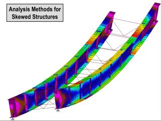
Choose Element Type • “Frames” should be 1-D elements • Use truss or beams • thickness each way should be < 1/20 of length • Thin structures • Maximum thickness should be < 1/10 of maximum dimension • Use plate or shell elements • Two dimensional solids • Axisymmetric model • Long through thickness model(plane strain) • Thin in-plane displacements (plane stress)
1-D Element Examples • House or building frame • Bridge truss network • Equipment support frames • Cable structure
Thin Structure Examples • Airfoil • Submarine hull and bulkheads • Sheet metal structures • Aircraft skin • Automobile body • Building walls, windows, etc • Food cans, bottles
Axisymmetric Solid Examples • High pressure tanks • Ball bearings • Nozzles • Nose cones • Pipes
Axisymmetric Shell Examples • Soda cans and bottles • Missile skin • Low pressure tanks • Paper plates
Plane Strain Models • Loading only in one 2-D plane • Structure is “cylindrical” through the thickness • 2-D plane is far from ends • Every 2-D section looks exactly the same • Structure does not deflect like a beam • Supports are the same along the length • Ends do not move axially, bend or twist • Generalized plane strain: each section can move axially, bend and twist.
Plane Stress Models • Structure is a thin flat 2-D plate • Loading is only in the plane of the 2-D plate • Through thickness stresses are negligible
Higher Order Plane Elements • Four Node Quad • Eight Node Quad
Higher Order Brick Elements • 8-Node Brick • 20-Node Element
Higher Order Elements • Corner & mid-side nodes • Quadratic displacements along edges • Corner nodes only • Linear displacements along edges • Mid-side node elements are more accurate • Mid-side node elements require less elements but have more degrees of freedom per element • Mid-side node elements can have more distortion and remain accurate
Element Distortion • Aspect ratio • Greatest element length divided by smallest • Linear elements can go to 5:1 to 10:1 • Quadratic elements can go to more than 20:1 • Vertex angles • Should be as close to 90 degrees as possible • Error is about 1/sin(vertex angle) • Degeneration • Collapsed nodes (quads to triangles & bricks to wedges and tetrahedrons) • Use special collapsed elements if possible
Solution Types • Static • Dynamic • Nonlinear • Special Types
Static Solution Examples • Maximum stresses • Stress concentrations • Fracture depends on maximum principal stress • Yielding • Thermal stresses • Specify coefficients of expansion • Specify strain free temperatures • Do not add boundary conditions that will unnecessarily constrain thermal expansion
Dynamic Solution Examples • Natural frequencies • Harmonic response – Response due to a sinusoidal input force or displacement, • Power Spectral Density • Response over many frequencies • Usually a probabilistic response • Transient response • For example: wave propagation and explosions • Time step must be specified
Nonlinear Response Examples • Stress stiffening and buckling • Mass softening • Gaps and friction • Highly nonlinear • Load steps cannot be large as gaps close • Inelastic analysis • Steps through yield stress must be small
Inelastic Response • Plastic yielding • Depends on von Mises stress (isotropic material) • Return from a maximum stress (tension or compression) is by Young’s modulus • Creep • Depends on von Mises stress (isotropic material) • Anisotropic materials are considerably more complicated • Includes single crystal components
Special Considerations • Super-elements can be used to model complex structures • Stiffness matrix from a detailed element grid is used • Interior nodes are eliminated • Cracks • Crack tips can be modeled by moving mid-side nodes to the quarter points • Rubber materials • Pressure becomes an unknown in addition to displacements