Download

1 / 30
750 likes | 2.11k Views
PILE FOUNDATION. STATIC METHOD FOR BORED PILES. Driven Piles - Advantages. Piles of any size, length and shape can be made in advance and used at the site. – rapid progress of work Driven into granular soil - compacts the adjacent soil mass - increase in bearing capacity

E N D
Driven Piles - Advantages • Piles of any size, length and shape can be made in advance and used at the site. – rapid progress of work • Driven into granular soil - compacts the adjacent soil mass - increase in bearing capacity • The work is neat and clean • Supervision of work at the site can be reduced to a minimum. • Storage space required is very much less. • In places where it is advisable not to drill holes for fear of meeting ground water under pressure. • For works over water such as piles in wharf structures or jetties.
Driven Piles - Disadvantages • Must be properly reinforced to withstand handling stresses during transportation and driving. • Advance planning is required for handling and driving. • Requires heavy equipment for handling and driving. • Since the exact length required at the site cannot be determined in advance, the method involves cutting off extra lengths or adding more lengths - increased cost of project • Driven piles are not suitable in soils of poor drainage qualities – Soil heaving or lifting • Where the foundations of adjacent structures are likely to be affected due to the vibrations generated by the driving of piles, driven piles should not be used.
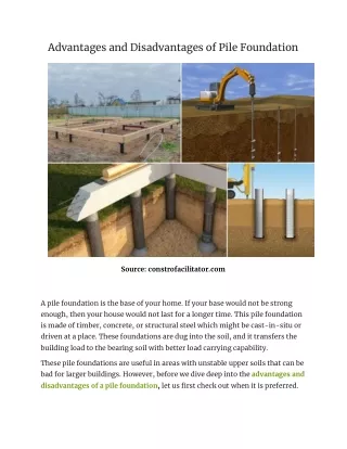
Bored Piles - Advantages • Piles of any size and length may be constructed at the site. • Damage due to driving and handling that is common in precast piles is eliminated in this case. • Ideally suited in places where vibrations of any type are required to be avoided to preserve the safety of the adjoining structure. • suitable in soils of poor drainage qualities
Bored Piles - Disadvantages • Requires careful supervision and quality control of all the materials used in the construction. • It needs sufficient storage space for all the materials used in the construction. • The advantage of increased bearing capacity due to compaction in granular soil that could be obtained by a driven pile is not produced by a cast-in-situ pile. • where there is heavy current of ground water flow or artesian pressure - very difficult to construct
Based on SPT Values • Displacement piles • Bored Piles Where Quultimate total load in kN Ncoraverage corrected SPT value below pile tip corrected average SPT value along the pile shaft Ab base area of pile in m2 (for H-piles including the soil between the flanges) As shaft surface area in m2
Bearing Capacity based on SCPT • Vander Veen's method • Schmertmann's method
Vander Veen’s Method • Ultimate load capacity of pile • Pile base resistance, • Ultimate skin friction
Schmertmann's method • Pile base resistance
Dynamic Formula - PRINCIPLE W - weight of the driving hammer h - height of fall of hammer Wh - energy of hammer blow Q - ultimate resistance to penetration S - pile penetration under one hammer blow Qus - resisting energy of the pile
DYNAMIC FORMULA • Hileys Formula • Engineering News
Hiley’s Formula • The energy loss E1 due to the elastic compressions of the pile cap, pile material and the soil surrounding the pile • The energy loss E2 due to the interaction of the pile hammer system
Hileys Formula - Energy losses • The energy loss E1 due to the elastic compressions of the pile cap, pile material and the soil surrounding the pile c1 = elastic compression of the pile cap c2 = elastic compression of the pile c3 = elastic compression of the soil.
Hileys Formula - Energy Losses • The energy loss E2 due to the interaction of the pile hammer system Wp = weight of pile Cr = coefficient of restitution
Hileys Formula where, ηh – Efficiency of the hammer
Hileys Formula Elastic compression c1 of cap and pile head Elastic compression c3 of soil Elastic compression c2 of pile
Hileys Formula Efficiency of pile hammer Coefficient of restitution Cr
Engineering News Formula W - weight of hammer in kg H - height of fall of hammer in cm s - final penetration in cm per blow (set) C - empirical constant The set is taken as the average penetration per blow for the last 5 blows of a drop hammer or 20 blows of a steam hammer C = 2.5 cm for a drop hammer C = 0.25 cm for single acting hammer
Pile Load Test • Load tests may be carried out on a working pile or a test pile • Pile load tests on a single pile or group of piles • For the determination of • Vertical load bearing capacity • Uplift load capacity • Lateral load capacity • Load test may be of two types • Continuous load test. • Cyclic load test.
Determination of Qu from Load-Settlement Curve • Qu, can be determined as the abscissa of the point where the curved part of the load-settlement curve changes to a falling straight line • Quis the abscissa of the point of intersection of the initial and final tangents of the load-settlement curve • Qais 50 percent of the ultimate load at which the total settlement amounts to one-tenth of the diameter of the pile for uniform diameter piles. • Qais sometimes taken as equal to two-thirds of the load which causes a total settlement of 12 mm • Qais sometimes taken as equal to two-thirds of the load which causes a net (plastic) settlement of 6 mm
Recap - Carrying Capacity of Piles • Using Theory (c,φ) • Using SPT value • Using SCPT Value • Using Dynamic Formula • Pile Load Test Static Formula In-situ Penetration Tests