Download
1 / 38
380 likes | 474 Views
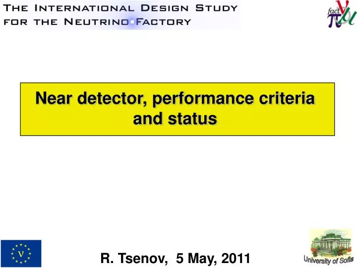
Near detector, performance criteria and status. R. Tsenov, 5 May, 2011. University of Sofia. Importance of flux knowledge for systematics. 2.5% error on flux makes big difference in CP coverage. CP violation discovery reach (3 σ CL) J.Tang, W.Winter, Phys.Rev.D80:053001,2009.

E N D
Near detector, performance criteria and status R. Tsenov, 5 May, 2011 University of Sofia
Importance of flux knowledge for systematics 2.5% error on flux makes big difference in CP coverage CP violation discovery reach (3σCL) J.Tang, W.Winter, Phys.Rev.D80:053001,2009
Charm production and τmeasurement (NSI) • Motivation: measure charm cross-section to validate size of charm background in wrong-sign muon signature (charm cross-section and branching fractions poorly known, especially close to threshold). • Motivation: tau production in near detector is a signal for non-standard interactions. Emulsion sheets or silicon strips? Vertex detector of high granularity is needed.
Cross section measurements Cross section measurements • Measurement of cross sections in DIS, QEL and RES. • Coherent and diffractive p, r, ... • Different nuclear targets: H2, D2 • Nuclear effects, nuclear shadowing, reinteractions Expected cross-section errors from T2K, Minerva, dominated by absolute flux error before Neutrino Factory. At NF, with modest size targets one can obtain very large statistics, but is <1% error achievable?
Near detector physics tasks • Determination of the neutrino flux (through the measurement of neutrino-electron scattering); • Measurement of the neutrino-beam properties that are required for the flux to be extrapolated with accuracy to the far detectors; • Measurement of the charm production cross sections; • Measurement of the νN deep inelastic, quasi-elastic, and resonant-scattering cross sections; • Search for Non Standard Interactions (NSI).
Near detector design requirements • Vertex detector for charm and τ production (NSI) • Low Z high resolution target for flux and cross-section measurement (nmand ne) • Magnetic field for muon momentum measurement (δp/p~1%?) • Muon catcher and capability for and e+/e– identification • Good resolution on neutrino energy for flux extrapolation (much better than Far Detector) – aspire to δE/E~1%
Determination of the neutrino flux • measure the muon beam in the straight sections: • beam intensity by Beam Current Transformer like device – good confidence that relative precision of few 10-3 can be reached (task on its own); • beam divergence by specialised device inside or around the beam pipe; • muon polarisation – averages out to zero; • calculate the neutrino flux: • muon decay properties incl. radiative corrections are extremely well known → we can rely on MC; • independent measurement of the neutrino flux in the Near detector – very important cross-check.
Projection method to the Far detector • Effect of fit accuracy from c2 for q13 and d between fitted value and true value • Standard method: calculated flux with floating normalistion • Projection method: fit using near detector flux to predict far detector Normal hierarchy: q13=1o, d=45o Slightly better fits using near detector projection: average residuals ~0.6s comparedto ~0.9s with the standard one
Neutrino Factory Near Detector(s) Decay straight dip angles of the two racetracks are 18° and 36°→ Near detectors will be at depths of 264 and 502 m, respectively. Eμ = 25 GeV ±80 MeV Straight section length = 600 m Muon angular spread 0.5 mrad 100
Block diagram design Near Detector design will have three sections: • High granularity detector for charm/tau measurement; • High resolution detector (Scintillating Fibres trackerorStraw Tube tracker) for precise measurement of the event close to the vertex; • Mini-MIND detector for muon measurement. ~15 m 3 m n beam 3 m High granularity detector High resolution detector Mini-MIND B~1 T
Neutrino flux from μ– decays through the detector at 100 m from the straight end scaled to 2.5x10²⁰μ– decays/year
Measurement of the neutrino flux by ν-escattering ν-e CC quasi-elastic scattering with singlemuon in the final state: Absolute cross-section can be calculated theoretically with enough confidence. Two processes of interest (available only for neutrinos from μ– decays): Production via annihilation Inverse Muon Decay (IMD) for 15 GeV νμ; it is ~10-3 of σtotal(νN) ν-e NC elastic scattering with singleelectron in the final state: sin2qW is known to better than 1% for this Q2 domain.
ν-e CC signal extraction (only a μ– in the final state) → discriminating variables • deposited energy around the vertex and • muon scattering angle θμ, or • = y, inelasticity, or • muon pT2 Tracker requirements: • must provide sufficient interaction rates → solid detector; • must be able to reconstruct the polar angle of the scattered muon with 0.5 mrad precision or better → low Z tracker; • must be able to measure the hadron recoil energy down to values of several MeV → precise calorimeter.
Polystyrene (1.06 g/cm3) A module = absorber & tracker station, 5.4 cm thick 20 modules, ~2.5 t A tracker station – horizontal and vertical layers, each has 4 fibre planes shifted with respect to each other; Scintillating fibres – 0.5 mm width (round or square); 24000 fibres per station (480 000 in total); 5 cm thick absorber, divided into 5 slabs to allow for more precise measurement of recoil energy near the event vertex; One must be able to measure deposited energy in a slab down to values of several MeV. SciFi tracker design • Rad. length X0 ~ 41 cm • RMS(θplane) = 0.2 – 0.4 mrad per module due to multiple scattering • Ultimately, with perfect space alignment of fibers, a position resolution of ~50 µm per station is achievable and angular resolution of ~ 0.5 mrad (obtained by GEANT4 simulations and Kalman filter reconstruction).
Signal extraction cut cut (for 0.25x10²⁰μ– decays) We can achieve ~1% uncertainty on the flux normalisation.
Background subtraction exploiting anti-νμ interactions No ν-e CC peak in anti-νμ interactions; Normalize the measured µ+ and µ– distributions in a range of the discriminating variable outside signal region to the decay ringµ– and µ+currents.The normalised µ+ distribution extrapolated into the signal region is used to evaluate the νμN→μ– X background to the ν-e CC peak; To be performed in a given Near detector it would require alternating of magnetic fields in the decay ring.
Exploiting inelasticity (~ θμ2Eμ) ν-e CC switched off extrapolation 1x10²⁰ muon decays per charge Exploitingθμorpt2 gives similar results. Uncertainty on the flux normalisation is below 1%.
Straw tube tracker design High resolution magnetised detector (HiResMn) – proposed for LBNE Near detector Builds on NOMAD experience and ATLAS TRT and COMPASS detector designs. S. Mishra
HiResMn absolute flux measurement via ν-e NC elastic scattering S. Mishra Signaland charged hadrons background LBNE flux! Resolutions in HiResMν ρ ≈ 0.1gm/cm3 Space point position ≈ 200μm Time resolution ≈ 1ns CC-events vertex: Δ (X,Y,Z) ≈ O(100μ) Energy in Downstream-ECAL ≈ 6%/√E μ-Angle resolution (~5 GeV) ≈ O(1 mrad) μ-Energy resolution (~3 GeV) ~ 3.5% e-Energy resolution (~3 GeV) ~ 3.5% • ν-e NC signal: single forward e– • Background: charged hadrons and • NC induced π° → γ → e– (e+ invisible) • Two-step Analysis: • Electron-ID by transition radiation detection • Kinematical cut on y ~ Pe(1-cosϴe) • It seems the background is benign (≤10-6).
High granularity vertex detector • Stack of OPERA-like emulsion sheets:150 sheets, overall volume ~500 cm3, mass ~ 1 kg, thickness - 4.6 cm (0.2 X0), capacity ~ 5000 neutrino events out of ~5x10⁵νμ CC interactions per year for this mass; • Silicon vertex detector like NOMAD-STAR detector:~50 kg, ~7×10⁵ charm events reconstructed per year, sensitivity for Pμτ < 3 × 10⁻⁶ at 90% C.L. NOMAD-STAR
Summary and outlook • Near detector(s) at the Neutrino factory is a valuable tool for neutrino flux measurement and standard and non-standard neutrino interactions study; • Set-up: high granularity vertex detector, high resolution tracker, muon catcher – the design is dictated mostly by requirements for flux measurement; • At least two options considered so far for any of the subdetectors. Silicon vertex detector+SciFi tracker+mini-MIND set-up is most advanced with respect to simulations; • Further tasks: • determination of the Near detector baseline design and full simulation; • determination of systematic errors from near/far extrapolation (migration matrices); • expectation on cross-section measurements; • other physics studies: electroweak parameters, PDFs, etc.; • sensitivity to non-standard interactions (τ-lepton production); • R&D efforts to validate technology (e.g. vertex detectors, tracking detectors, etc.).
Simulation Processes included in GENIE Near detector flux simulation Quasi-elastic scattering Elastic NC scattering Baryon resonance production in CC and NC Coherent neutrino-nucleus scattering Non-resonant inelastic scattering (DIS) Quasi-elastic charm production Deep-inelastic charm production Neutrino-electron elastic scattering and inverse muon decay (IMD) C. Andreopoulos et al., The GENIE Neutrino Monte Carlo Generator, arXiv:0905.2517 flux driver GENIE http://www.genie-mc.org arXiv:0905.2517 ROOT file GEANT4 ROOT file (Simple) digitization Reconstruction
Simulation of the neutrino beam Properties of the neutrino beam
Quasielastic scattering off electrons • Distributions of the neutrinos over their energy and polar angle at the position of the near detector for the two polarizations of the decaying muons.
Neutrino flux per unit radius Relative units
Monitoring of the muon beam polarization The leptonoc interactions of the neutrinos can be used to monitor the polarization of the muon beam in the storage ring. The plot shows the number of leptonic events in 5 m long polystyrene detector as a function of the distance from the neutrino beam axis for three different polarizations of the muon beam in the storage ring and for 1021 muon decays (1 year). It is clear that the variation of the distribution of the events because of the different polarization of the muon beam is much bigger than the statistical errors.
Secondary muon distributions 0.5 mrad spread of the muon beam
ν-e NC elastic scattering S. Mishra sin2qW is known to better than 1% for this Q2 domain.
Assumptions for digitization and reconstruction Digitization Fiber signal is proportional to energy deposition corrected for attenuation and smeared with a Gaussian with σ/E = 25% (too optimistic?) Slab signal is proportional to total energy deposition, smeared with σ/E = 5% (optimistic?) Muon momentum is measured with an error of 1% (not crucial for the moment, can be relaxed) Event vertex slab is found with high certainty.
Tracking capabilities Rad. length X0 = 41.31 cm Each module is 5.4 cm thick RMS(θplane) = 0.2 – 0.4 mrad per module Ultimately, with perfect space alignment of fibers, a position resolution of ~50 µm per station is achievable and angular resolution of ~ 0.5 mrad
ν-N background rejection Energy deposition in the first illuminated absorber (5 cm thick) vs. reconstructed muon angle
Background rejection Elaborated cuts : < 1 MeV (or no) total backward energy deposition < 2.5 MeV energy deposition averaged over illuminated slabs < 4 MeV energy deposition in event vertex slab
Discriminating on θμ 1x10²⁰ muon decays/charge/year
Discriminating on pt2 1x10²⁰ muon decays/charge/year