Download
1 / 31
310 likes | 467 Views
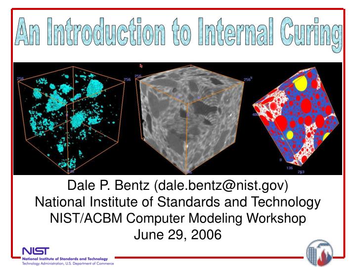
An Introduction to Internal Curing. Dale P. Bentz (dale.bentz@nist.gov) National Institute of Standards and Technology NIST/ACBM Computer Modeling Workshop June 29, 2006. Collaborators. NIST - Mr. Max Peltz and Dr. Kenneth A. Snyder Mr. Thomas A. Holm (ESCSI)

E N D
An Introduction to Internal Curing Dale P. Bentz (dale.bentz@nist.gov) National Institute of Standards and Technology NIST/ACBM Computer Modeling Workshop June 29, 2006
Collaborators • NIST - Mr. Max Peltz and Dr. Kenneth A. Snyder • Mr. Thomas A. Holm (ESCSI) • Mr. John W. Roberts (Northeast Solite) • Pennsylvania State University • Profs. Phillip M. Halleck and Abraham S. Grader • Technical University of Denmark • Profs. Mette Geiker, Ole M. Jensen, and Pietro Lura
Question: What is internal curing (IC)? Answer: As being considered by ACI-308, “internal curing refers to the process by which the hydration of cement occurs because of the availability of additional internal water that is not part of the mixing water.” For many years, we have been curing concrete from the outside in, internal curing is for curing from the inside out. Internal water is generally supplied via internal reservoirs, such as saturated lightweight fine aggregates, superabsorbent polymers, or saturated wood fibers.
Question: What are the main benefits that IC can provide? Answers: - Reduced autogenous deformation and less early-age cracking - Maintenance of a higher internal RH, enhanced (long term) hydration and strength development
Early-Age Cracking Contributors • Thermal Effects • Hydration heat can raise concrete temperature significantly (causing expansion), subsequent thermal contraction during cooling can lead to early-age (global or local) cracking if restrained (globally or locally) • Autogenous Shrinkage • In lower w/cm concretes, if sufficient curing water can not be supplied externally, the chemical shrinkage that accompanies the hydration reactions will lead to self-desiccation and significant autogenous shrinkage (and possibly cracking)
Some Terminology(from RILEM ICC committee) • Chemical shrinkage • An internal volume reduction that is the result of the fact that the absolute volume of the hydration products is less than that of the reactants (cement and water); can be on the order of 10 % by volume; new (2005) ASTM standard test method is C1608 • Self-desiccation • The reduction in the internal relative humidity (RH) of a sealed system when empty pores are generated. • Autogenous shrinkage • The external (macroscopic) dimensional reduction of the cementitious system under isothermal, sealed curing conditions; can be 100 to 1000 microstrains
Example of Chemical Shrinkage (CS) Hydration of tricalcium silicate C3S + 5.3 H C1.7SH4 + 1.3 CH Molar volumes 71.1 + 95.8 107.8 + 43 CS = (150.8 – 166.9) / 166.9 = -0.096 mL/mL or -0.0704 mL/g cement For each lb (g) of tricalcium silicate that reacts completely, we need to supply 0.07 lb (g) of extra curing water to maintain saturated conditions (In 1935, Powers measured a value of 0.053 for 28 d hydration – 75 %)
From Chemical Shrinkage to Autogenous Shrinkage • CS creates empty pores within hydrating paste • During self-desiccation, internal RH and capillary stresses are both regulated by the size of the empty pores being created • These stresses result in a physical autogenous deformation (shrinkage strain) of the specimen • Analogous to drying shrinkage, but drying is internal
Question: Why do we need IC? Answer: Particularly in HPC, it is not easily possible to provide curing water from the top surface (for example) at the rate that is required to satisfy the ongoing chemical shrinkage, due to the extremely low permeabilities that are often achieved in the concrete as the capillary pores depercolate. Capillary pore percolation/depercolation first noted by Powers, Copeland and Mann (PCA-1959).
Question: How does IC work? Answer: IC distributes the extra curing water throughout the entire 3-D concrete microstructure so that it is more readily available to maintain saturation of the cement paste during hydration, avoiding self-desiccation (in the paste) and reducing autogenous shrinkage. Because the autogenous stresses are inversely proportional to the diameter of the pores being emptied, for IC to do its job, the individual pores in the internal reservoirs should be much larger than the typical sizes of the capillary pores (micrometers) in hydrating cement paste and should also be well connected (percolated).
Cement paste Water reservoir
Question: How can the effectiveness of IC be quantified? Answer: By direct and indirect experimental measurements including – internal relative humidity (RH) autogenous deformation compressive strength development degree of hydration restrained shrinkage or ring tests 3-D X-ray microtomography
Internal RH, How to measure it? On small volumes of mortar in sealed containers using Rotronic Hygroscope DT RH stations (at Technical University of Denmark) Grasley, Lange, and D’Ambrosia at UIUC have recently developed a small insitu temperature/RH sensor for use in (field) concrete
Internal RH ResultsMortars with Internal CuringLWA = saturated lightweight aggregatesSAP = superabsorbent polymerFSF = control with fine silica fume w/cm = 0.35
Autogenous Deformation, How to measure it? One way is with custom-built digital dilatometers(Prof. O.M. Jensen - DTU) Specimens sealed in corrugated polymer tubesand stored at constant temperature Method under consideration for standardization by ASTM C09.68
Autogenous Deformation Results w/cm = 0.35
Autogenous Deformation Results IC added via fine LWA to increase total “w/c” from 0.30 to 0.38 or 0.40 Note – chemical shrinkage of pozzolanic reaction of silica fume with CH is ~0.22 g water/g silica fume or about 3.2 times that of cement
Autogenous Deformation Results IC added via fine LWA to increase total “w/c” from 0.30 to 0.38 Note – chemical shrinkage of slag hydraulic reactions is ~0.18 g water/g slag or about2.6 times that of cement
Degree of Hydration and Strength w/cm = 0.35 mortars, sealed curing w/cm = 0.3 HPM with silica fume blended cement
Three-Dimensional X-ray Microtomography • X-ray microtomography allows direct observation of the 3-D microstructure of cement-based materials • Example: Visible Cement Data Set http://visiblecement.nist.gov • In October 2005, experiments were conducted at Pennsylvania State University to monitor three-dimensional water movement during internal curing of a high-performance mortar over the course of two days
After mixing 1 d hydration 2 d hydration All images are 13 mm by 13 mm Aqua indicates drying Red indicates wetting Subtraction: 1 d – after mixing
Three-Dimensional X-ray Microtomography 2-D image with water evacuated regions (pores) overlaid on original microstructure (4.6 mm by 4.6 mm) Three-dimensional subtracted image of 1 d hydration – initial microstructure showing water-filled pores that have emptied during internal curing (4.6 mm on a side)
Three-Dimensional X-ray Microtomography Empty porosity within LWA from analysis of 3-D microtomography data sets scales “exactly” with measured chemical shrinkage of the cement for first 36 h of curing
Questions to Consider When Using IC • How much water (or LWA) do I need to supply for internal curing? • How far can the water travel from the surfaces of the internal reservoirs? • How are the internal reservoirs distributed within the 3-D concrete microstructure? Answers May be found at the NIST internal curing web site:http://ciks.cbt.nist.gov/lwagg.html
http://ciks.cbt.nist.gov/lwagg.html Menu for Internal Curing with Lightweight Aggregates 1)Calculate Lightweight Aggregates Needed for Internal Curing 2)Estimation of Travel Distance of Internal Curing Water 3)Simulate Mixture Proportions to View Water Availability Distribution 4)View Water Availability Distribution Simulation Results 5)Learn more about FLAIR: Fine Lightweight Aggregates as Internal Reservoirs for the autogenous distribution of chemical admixtures 6)View presentation on internal curing made at 2006 Mid-Atlantic Region Quality Assurance Workshop Link to Workshop homepage 7)Internal Curing Bibliography 8)Direct Observation of Water Movement during Internal Curing Using X-ray Microtomography
Question:How much water (or LWA) do I need to supply for internal curing? Answer: Equation for mixture proportioning (Menu selection #1) MLWA =mass of (dry) LWA needed per unit volume of concrete Cf =cement factor (content) for concrete mixture CS =(measured via ASTM C 1608-05 or computed) chemical shrinkage of cement αmax =maximum expected degree of hydration of cement, [(w/c)/0.36] or 1 S =degree of saturation of LWA (0 to 1] when added to mixture øLWA = (measured) absorption of lightweight aggregate (use desorption measured at 93 % RH (potassium nitrate saturated salt solution) via ASTM C 1498–04a)
Question:How far can the water travel from the surfaces of the LWA? Answer: Equation balancing water needed (hydration) vs. water available (flow) (Menu selection #2) “Reasonable” estimates --- early hydration ---- 20 mm middle hydration --- 5 mm late hydration --- 1 mm or less “worst case” --- 0.25 mm (250 μm) Early and middle hydration estimates in agreement with x-ray absorption-based observations on mortars during curing
Question:How are the internal reservoirs distributed within the 3-D concrete microstructure? 30 mm by 30 mm Answer: Simulation using NIST Hard Core/Soft Shell (HCSS) Computer Model (Menu selections #3 and #4) Returns a table of “protected paste fraction” as a function of distance from LWA surface Yellow – Saturated LWA Red – Normal weight sand Blues – Pastes within various distances of an LWA
Question: What does the future hold? Answer: - Likely that more state DOTs and concrete ready-mix producers will begin to evaluate internal curing - Investigation of possible “air void” system provided by empty internal reservoirs - Investigation of possible enhanced workability (retention) in systems with internal curing - Usage of internal reservoirs to distribute chemical admixtures as well as water (SRAs, corrosion inhibitors, ASR mitigation admixtures, and phase change materials) FLAIR – Fine Lightweight Aggregates as Internal Reservoirs (Menu selection #5 on NIST internal curing web site; being investigated by W.R. Grace, Sika, and Maxit)
Question: Who (else) is active in this area of research/application? Answer: - NIST - NRC/Canada (Dr. Daniel Cusson) - Cleveland State University (Prof. Delatte for Ohio DOT) - RILEM-ICC (Dr. Kosta Kovler – Technion, Israel) - Tennessee Tech Univ. (Prof. Ben Mohr) - Technical University of Denmark (Profs. Ole Jensen and Pietro Lura – superabsorbent polymers) -University of Toronto (Prof. Hooton and Hoa Lam) - TXI (job in Texas, spring 2005 – 238,000 yd3 concrete) - U.S. Concrete (specified density concrete)