Download
1 / 62
630 likes | 725 Views
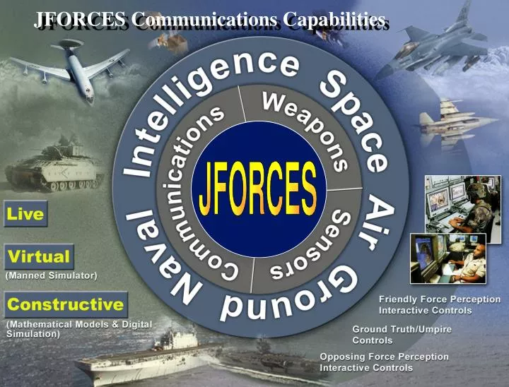
JFORCES Communications Capabilities. JFORCES DIMENSIONS. Structural (Who). Spatial (Where). Functional (What). Temporal (When). Procedural (How). Constructs Super Sets/Domains Collections Objects Entities Systems Subsystems Components Parameters.

E N D
JFORCES DIMENSIONS Structural (Who) Spatial (Where) Functional (What) Temporal (When) Procedural (How) Constructs Super Sets/Domains Collections Objects Entities Systems Subsystems Components Parameters Environment Space Atmosphere Surface Ground Sea Sub-surface Ground Sea Functions Exist Organize/Structure Act Move Deploy Posture Command Direct Interact Sense Track Communicate Evade Engage Defend Kill Controls Timing Synchronization Controls Events Triggers Rules Processes Strategies Doctrine Create/Define Edit/Modify Delete Archive Retrieve Process/Analyze Summarize Display Requirements Interfaces Inputs Outputs Transitivity CONTEXT Inheritance Encapsulation
Enhancements/Options: • Additional RAM • Graphics Accelerator Boards • Image Processing Boards • Other Special-purpose Adjuncts • Interactive Object Controls/Displays • Interactive Situational Displays • Simulation Controls - Start - Reverse - Stop - Re-plan Real Objects/Nodes - Pause - Checkpoint - Replay Event or - Fast Forward Time-Step Scenario Archives Log-file Archives Other Simulators Real Software Other Simulations Databases Application Libraries • Motion Utilities • Functional Algorithms Wide Area Object Actions Dynamic Inter-actions Networks • Data Transform Utilities • Process Definitions/Rules The JFORCES Framework Provides Modules and Inter/Intra-Module Services to Support Architectural-Level Evaluation Based on Physics-based Engineering-Level Models "HOSTILE/OPPOSING FORCE" C2 "FRIENDLY" COMMAND & CONTROL COMMUNICATIONSMODULE ENVIRONMENT MODULE SIM DEVELOPMENT AUTOMATED DIRECTION/CONTROL MODULE • Create Object Classes • Local States • Propagation • Media States • Network Protocols • Determination of Communication • Events • Define Entities • Earth - Terrain • Input/Edit Parameters - Features • Process Rules & Sequences • Select Application Fidelity • Cartographic Utilities • Strategies • Atmospheric Phenomena • Doctrine • Exo-atmospheric Phenomena • Tactics SCENARIO GENERATION • Select Environment/Granularity OBJECTS MODULE Simulation Executive FUNCTIONS/DYNAMICS MODULE • Define Object Associations • Define Object Missions • Object States (Including Systems, Subsystems & Components) • Define Route/Motion Specifications • • Simulation Runtime Controls • Message-Passing Controls • Event Calendar Management • Module Controller • Network Controls • Define Scripted Events • Object Actions - Location - Orientation • Define Object Initial States - Awareness - Thresholds • Define/Select Rules • Object Interactions • Motion/Propulsion Utilities • Object Awareness PREVIEW Open System • Verify Objects/Entities (Menu/Tables) SENSOR MODULE LINUX & UNIX • Animate/Verify Motion, Interactions, Distributed Runtime Databases Timing & Spatial Relationships GL graphics • Object Sensing • Verify Scripted Events, Missions/Routes • Acquisition • Tracking & Correlation GRAPHICAL USER INTERFACE • Multi-sensor Fusion • Determination of Detection Events DATA ANALYSIS EXECUTION LOG FILES StandardGraphics Workstation/PC • Insert Data Probes • Set Data Logging Specifications LOGIC/REASONING MODULE • Set "Watchdog" Specifications • Define Capture Specifications • Intelligent Processes/Rules • Cognitive Processes/Rules • Classification Rules ANALYTICAL MODULE RUNTIME CONTROLS • Interpretive Logic Rules • Situation Assessment Rules • Statistical Packages • Presentation Graphics • After-Action Debrief Static Database ManagerInterfaces CONFIG. MANAGEMENT EXTERNAL GATEWAYS • Set Configuration Specifications for Nodes & Networks • Input Runtime Specifications (e.g., Timing & Synchronization) • Invoke Archive Management Tools • Optimize Parallel Processing Topology • Rapid Prototype Operator Interfaces
TRAAC Definitions Timeliness C4ISR Messages are received within time increments that are appropriate to support conduct and execution of planning and operations that ensure mission success Relevance C4ISR Messages are transmitted to the appropriate command authority, via available media with the correct priority, only when required to support the conduct and execution of current plans & operations and when required to update correct situation awareness or insure mission success Availability C4ISR Messages may be pushed or pulled from designated sources whenever required to support plans & operations at a level to achieve mission success Accuracy C4ISR Messages provide the appropriate degree of correct data required to support plans & operations at a level to ensure mission success C4ISR Messages provide the level of content and detail necessary for the proper conduct and execution of plans and operations to assure mission success Completeness
JFORCES Communications Analysis Options: • Communications Service and Customer Demand Analysis • Adaptive Network Link Analysis • Packet-level/Protocol Analysis • Requires Federation/Integration • Application Options include OpNet/QualNet, Network 2.5, other • Optional Communications Modes/Military Utility Analysis • Use JFORCES ISR/Sensor Module to Define Communications Loading • if the value of (n*ISR messages = x*Mbps) can be established for each • critical C2 message type; else • 2. Input communications data loadings through JFORCES Mission Planner
Communications Service and Customer Demand Analysis • Primary Purpose: • Evaluate the capabilities of alternative Communications Architectures/Systems/Subsystems/Components • to meet various user demand loading scenarios • Typical Elements: • Link Budgets • Operational Duty Cycles • Ephemeredes for Space Assets (CommSats and Relays) • Parameters that define System/Subsystem/Component Capabilities • Alternative Bandwidth Services to Satisfy AISR Mission Requirements • Assumptions regarding message quality, security, and other measures of Performance (MOPs) • Service Satisfaction and Bandwidth Capacity are primary MOEs • Relevant JFORCES Experience and Developed Capabilities • Support to NSSO (COMM/FIO) Analysis of Alternatives (AOA) for Airborne Intelligence/Surveillance & Reconnaissance • Developed accredited worldwide ISR collection simulation for Joint DoD and Intelligence Community Users • (2006 thru 2025 AISR and Space Satellite Programs of Record and all major planned programs/initiatives) • Cross-model V&V with Aerospace CASA and Boeing BEAST models • SCI database, scenarios and analytical results (Reference Baseline and numerous Development Alternatives)
JFORCES Graphical Route & Duty Cycle Planner Assets assigned to this route will attempt to communicate beginning at leg #3 for 1000 minutes each time the route is flown
Typical Communications Supply/Demand Input For Each Airborne User Mission & Each Communications Subsystem: Customer Name/Vehicle Type User Platform Initial Take-off Time Altitude Speed Route: Waypoint to begin communications activity Waypoint to end communications activity Landing time/place Duty Cycle (Rates/Repetitions) Communications Medium: User Transmit Frequency (Mhz) Server Max./Min. Receive/ Transmit Frequency Bandwidth (KHz) Max. Data rate (Mbps) # Beams/Antenna # Simultaneous User Contacts Noise Temp (degK)
JFORCES Analytical Outputs Satellites that have the number of antenna beams and compatible bandwidth to meet data rate and bandwidth capacity requirements provide services to current and future versions of airborne ISR platforms IAW user priorities And allocated loading requirements Output reports correctly depict dynamic relationships between airborne assets and communication satellites
JFORCES Interactive Communications Interface Display • Provides depiction of geospatial relationships between assets • - Beam shape/dimensions • - Communications closings • - User platforms in satellite • beam footprint(s) • Visually verifies analytical • Inputs & results • Allows analyst to control simulated assets and to inject events & state changes
JFORCES Analytical Outputs Outputs depict demand in terms of critical communications resource utilization and present the shortfalls in the current architecture in order to identify requirements for full demand loading satisfaction.
JFORCES Analytical Outputs Analytical outputs provide data describing the dynamics of communications demand by band, by user type, and by individual customer and the relative robustness of the architecture, systems, subsystems and components available to respond to the demand.
JFORCES Analytical Outputs Summary reports detail communications capability and overall requirement satisfaction for each platform/subsystem in the scenario (by coverage and by bandwidth capacity).
JFORCES Analytical Outputs Graphical displays describe causes and duration of failures to communicate as a result of insufficient geographical coverage, insufficient bandwidth, and/or pre-emption by users with higher priority.
JFORCES Analytical Outputs Comparing Communications Architectures Three alternative communication Architectures are shown; each with a different level of user satisfaction…((total serviced hours/total hours of demand) X 100). This empirical MOE is included in Cost, Scalability,
JFORCES Adaptive Communications Network Analysis • Primary Purpose: • Evaluate the capabilities of alternative Communications Networks to meet various user demand loading scenarios • & identify likely impact of delays or critical message corruption on outcomes of military scenarios • Typical Elements: • Operational Duty Cycles • Ephemeredes for Space Assets (CommSats and Relays) • Parameters that define System/Subsystem/Component Capabilities at each network node • Highly articulated Network routing and processing definitions • Parameters affecting message quality, security, and other measures of Performance (MOPs) • Message Quality and Network Processing Delays are primary MOEs • Relevant JFORCES Experience and Developed Capabilities • Support to Decision Support Center for New Triad Communications Study • Developed Network Analysis tools for simulation & Evaluation of Joint DoD New Triad Communications Networks • Developed MOEs & MOPs for Alternative Communications Network Evaluation in Nuclear Threat Environments • Characterized Threat Environment for New Triad Joint Communications Network Evaluations
sat2net3 source Key event detection Sat3Net2 Sat1Net2 Sat1Net2 Sat2Net2 sat1net2 sat3net1 NCA destination Sat1Net2 sat1net3 Sat3Net2 sat2net1 sat2net2 Sat1Net0 Sat1Net2 Sat1Net2 sat1net1 Sat1Net2 sat3net3 JFORCES Adaptive Communications Network Analysis JFORCES network analysis functionality begins when a critical event occurs, for example when an emitter is detected on a source satellite. JFORCES objective is to ascertain if the communications networks can route the information to a decision maker destination reliably and quickly.
sat2net3 source Sat3Net2 Sat1Net2 Sat1Net2 Sat2Net2 sat1net2 relay relay relay sat3net1 NCA destination Sat1Net2 sat1net3 Sat3Net2 sat2net1 sat2net2 Sat1Net0 Sat1Net2 Sat1Net2 sat1net1 Sat1Net2 sat3net3 JFORCES Adaptive Communications Network Analysis JFORCES analyzes complex communications environments, notably the interoperability between satellites, constellations, relays and ground links. Multiple routing options between satellites as well as communications suites are evaluated for the most reliable route as well as overall source-to-destination reliability.
L2 Tertiary Secondary Primary – Route 1 Sat Net 3 (source) Sat Net 2 Sat Net 1 Ground Net 0 … NCA (destination) L3 NCA Relay Sat1Net2 Configuration General Asset Orbit, Type, … Comm Suites 1: name , type 2: name, type … L4 Ground Net 1 Communications Modeling Methods Routed Through Tiers of Comm Protocols for Various Missions Evaluating Redundancy and Delays • Loading from Scenario & non-Scenario Messages with Appropriate: • Size • Content • Format (optional) Each Consisting of Specific Assets with Detailed State and Configuration Specification • Each with one or more Comm Suites with Details to Support Detailed Analysis of: • Throughput Success • Delays • Propagation Evaluation in Adverse Environments
Baseline C4ISR Architecture Strategic/Operational Support BA C2 NC Information Flow to CJTF/JFCCs MILSTAR DSCS Commercial Ka Band D C2 JSTARS AWACS C OV-2 UFO DSCS D JTIDS GCCS SIPRNET GBS IBS DDS C NMCC MGS CGS CJTF T/C/D JFCCs COCOMs DCGSs JIC National Agency T/C/P/E/A/D T/E/A T/C/P/E/A/D JWICS Information Store Decision Delay Information Delay Transmission Delays Also Occur at Selected T/C/P/E/A/D Nodes T/C/P/E/A/D – Tasking/Collection/Processing/Exploitation/Analysis/Dissemination C2 – Command and Control
Sat Net 3 Route4 Link1 Route2 Route3 L1 Sat Net 2 Route1 L2 Link2 Sat Net 1 L3 Key event detection Link3 NCA Relay Link4 Relay L4 Ground Net 1 Ground Net 0 JFORCES Adaptive Communications Network Analysis JFORCES analyzes complex communications environments, notably the interoperability between satellites, constellations, relays and ground links. Multiple routing options between satellites as well as communications suites are evaluated for the most reliable route as well as overall source-to-destination reliability.
Route4 Link1 Route2 Sat1Net2 Configuration General Orbit Type … Comm Suites 1: name , type 2: name, type … Ancillary Information Encryption Ground Ctl Station Route3 L1 Route1 L2 Link2 L3 Key event detection Link3 NCA Relay Link4 Relay L4 Ground Net 1 Ground Net 0 JFORCES Adaptive Communications Network Analysis Sat Net 3 Sat Net 2 Sat Net 1 Configuration information will be stored for each link in a communications network.
JFORCES Adaptive Communications Network Analysis Sat Net 3 Route4 Communications Directive Chain Link1 Route2 Route3 L1 Sat Net 2 Route1 L2 Tertiary Secondary Link2 Primary – Route 1 Sat Net 3 (source) Sat Net 2 Sat Net 1 Ground Net 0 NCA (destination) Sat Net 1 L3 Key event detection Link3 NCA Relay Link4 Relay L4 Ground Net 1 Ground Net 0 Analyzing message routes will be based on directive chains – including pre-assigned message routes based on a network’s ability to communicate with other networks. Any number of directive chains may be defined to analyze the effectiveness of alternate routes. JFORCES will analyze system health every test interval by evaluating the chains in a pre-defined order.
JFORCES Adaptive Communications Network Analysis Directive Chains Sat Net 3 Tertiary Route Route4 Secondary Route Link1 Route2 Primary – Maintenance Primary – Communications Primary – Damage Control Route3 L1 Sat Net 2 Route1 L2 Link2 Sat Net 1 L3 Key event detection Link3 NCA Relay Link4 Relay L4 Ground Net 1 Ground Net 0 Directive chains will be supported for functions other than communications. Analysis of network health will also include directive chains to support the order of events required to restore the network from an event trigger. The analysis addresses five critical functions: Force mgmt (FM), Assignment, Training, Deployment, Maintenance and Logistics, as the information is provided. It will provide outcome statistics based on analysis in regular intervals, with logistical considerations including locating applicable ground control station(s) and acquiring repair authorization, to assessments of point attacks and area-wide attacks.
JFORCES Adaptive Communications Network Analysis Sat Net 3 Route4 Link1 Route2 Route3 L1 Sat Net 2 Route1 L2 Link2 Sat Net 1 L3 Key event detection Link3 NCA Relay Link4 Relay L4 Ground Net 1 Ground Net 0 In the event of an outage, for example an ASAT destroying or disabling a satellite, JFORCES will analyze the best alternate route(s) and evaluate the loss in terms of overall system health. This analysis also applies to outages due to a failure on the satellite, jamming, or NUDET.
JFORCES Adaptive Communications Network Analysis Sat Net 3 Route4 PCMR=99.9 Link1 Route2 Route3 L1 Sat Net 2 Route1 L2 PCMR=99.8 Link2 Sat Net 1 L3 Key event detection PCMR=99.5 Link3 NCA PCMR=99.0 Link4 Relay Relay L4 Ground Net 1 Route 1 PCMR=98.2 Ground Net 0 JFORCES analyzes Probability of Correct Message Receipt(PCMR) reception from end to end, as well as the individual links between each relay point. For example in this illustration, Sat2Net3 detects an event. On Route1, a PCMR will be calculated at Sat2Net2 for Link1, Sat3Net1 for Link2, as well as the PCMR at the destination (the whole route). Where multiple comm suites apply, PCMR’s will be calculated for each comm suite. Values are based on environmental conditions, including satellite condition, nudet, and jamming.Probability of Acceptable Message can be distinguished from PCMR’s if desired.
JFORCES Adaptive Communications Network Analysis Sat Net 3 Route4 PCMR=99.9 Link1 Route2 Route3 Sat Net 2 PCMR=99.9 L1 Route1 PCMR=99.0 L2 PCMR=99.8 Link2 Sat Net 1 Key event detection PCMR=99.6 L3 PCMR=99.5 Link3 NCA PCMR=99.0 Link4 Relay Relay PCMR=99.4 L4 Ground Net 1 Route 1 PCMR=98.2 Ground Net 0 Route 2 PCMR=97.9 Redundancy will be handled as established criteria through multiple routes to the destination. Where Route 1 and 2 may provide 98.2% and 97.9% PCMR, their composite PCMR will be 99.96%: PCMR Route 1 = 98.2%, so PF Route 1 = 1.8% PCMR Route 2 = 97.9%, so PF Route 2 = 2.1% PCMR Combined & Independent = 100*(1-.018*.021) = 99.96%
JFORCES Adaptive Communications Network Analysis Sat Net 3 Route4 PCMR=99.9 Link1 Route2 Route3 Sat Net 2 PCMR=99.9 L1 Route1 PCMR=99.0 L2 PCMR=99.8 Link2 Sat Net 1 Key event detection PCMR=99.6 L3 PCMR=99.5 Link3 NCA PCMR=99.0 Link4 Relay Relay PCMR=99.4 L4 Ground Net 1 Route 1 PCMR=98.2 Ground Net 0 Route 2 PCMR=97.9 In some cases the PCMRs are not independent, but share resources. In this case an alternate combined probability of comm failure is compared. Where: Pf Combined & Independent = 100*(1-.018*.021) = 99.96% Given a .1% shared resource: Pf Combined, 0.1% Shared Pf = (100-0.1)*(1-.017*.020) = 99.866%
JFORCES Adaptive Communications Network Analysis Sat Net 3 Route4 PCMR=99.9 Link1 Route2 Route3 Sat Net 2 PCMR=99.9 L1 Route1 PCMR=99.0 L2 PCMR=99.8 Link2 Sat Net 1 Key event detection PCMR=99.6 L3 PCMR=99.5 Link3 NCA PCMR=99.0 Link4 Relay Relay PCMR=99.4 L4 Ground Net 1 Route 1 PCMR=98.2 Ground Net 0 Route 2 PCMR=97.9 JFORCES can also analyze PCMR within the guidelines of acceptable delivery time to destination. Delays can be calculated in to the analysis. While instantiation and recognition delays can be a factor, JFORCES will only analyze transmission and relay delays.
JFORCES Adaptive Communications Network Analysis • Study Methods • Each initial point in a subnet is be considered a potential data source from the #1 (source subnet) directive chain. • in the same way, each end point/destination in the last directive chain subnet, is a potential sink • For each directive chain the analyst specifies a test interval. • A communication from each potential data source will be tested to any destination (sink) at every test interval.
JFORCES Adaptive Communications Network Analysis Healthy system 99.9% PCMR 99.5% time The JFORCES analysis will be summarized into brief displays and/or reports. If Mission Criteria specifies 99.9% for a healthy system, then we will detect when a network can maintain that level of reliability from a data source to the destination.
JFORCES Adaptive Communications Network Analysis Healthy system 99.9% PCMR 99.5% Satellite Reliability in the Network Distribution best 25% median time 75% worst 95% If greater detail is desired to reflect the health of the system, JFORCES could provide detail for any given point in time on the summary chart, by indicating the reliability of all of the satellites in the network at that given time, with a best, median, and worst case noted.
JFORCES Adaptive Communications Network Analysis Healthy system add Sat1 Net3 failure 99.9% add Sat 4 Net0 failure PCMR add Net3 Sat2 99.5% time Additional analysis can be performed to evaluate the reliability of communications given a particular satellite failure, or two, or three simultaneous satellite failures.
JFORCES Adaptive Communications Network Analysis Mission Success Criteria 99.0% 99.3% 99.5% 99.9% Situation Healthy System 100% 100% 100% 95% Sat1Net3 failure 100% 98% 95% 80% Sat 4 Net0 failure 98% 95% 93% 77% Net3 Sat2 failure 89% 85% 78% 60% Ultimately we can produce a chart indicating the probability of acceptable reliability based on the particular test situations and the criteria provided to indicate mission success. The 93% in the 99.5% column, row “Sat 4 Net0 failure”, indicates that if the mission success criteria has been indicated to be 99.5%, then the System will be reliable only 93% of the time when the system has a Sat4 Net0 AND Sat1 Net3 failure.
JFORCES Adaptive Communications Network Analysis Mission Success Criteria can be reported for multiple conditions and architectures for comparison. Architecture C: Architecture B: Architecture A:
Loading the Test Data into JFORCES • Data inputs can be broken down into: • Scenario data (probably already set, so we’ll ignore it for now) • Communications Suite Data • Platform Definitions • Communications Suite characteristics • Network Definition
Communication Suite Data • First requirement is for a Communications Suite to Platform Type Map • We can read this in from a simple flat file (preferably comma separated) • Limitations • Platform name must be no longer than 16 characters • Basic Platform Definition (e.g. is it a ground base or a satellite) must be provided • Communications Subsystem name must be no longer than 16 characters • Communications data (defined below) must be roughed out, though subsequent updates are easily made. • Communications Suite Definition Must be in Accordance with Stratcam Requirements • (described on the next page)
Network Definition Networks (and associated tests) are defined in a three-tier approach, each with a related database table. The info below is just a review to the approach described earlier in this presentation. Tests – This defines the tests to be run, success criteria, and test interval Directives – This defines the series of networks to used to accommodate a function (e.g. satellite maintenance or Early Warning). This includes the networks to be used, how they’re to be employed, the order of communications, and any alternate routing that can be employed Network Assets – This specifies all entities that are part of a named network. A network is not necessarily a complete route to accomplish a directive; instead it can just be a set of entities used to relay the message through one part of the communications path.
Packet-level and Protocol Analysis Primary Purpose: Evaluate the design and performance of alternative Communications Architectures/Systems/Subsystems/Components Including message processing and node design issues at the network nodes Typical Elements: Network Protocols and message processing parameters Processor and peripheral hardware/software descriptions and parameters Parameters that define Network System/Subsystem/Component Capabilities Highly detailed hardware/software concepts related to message quality, security, and other measures of Performance (MOPs) Message management, processing delays, message delivery and quality measures are primary MOEs Relevant JFORCES Experience and Developed Capabilities Developed and implemented mature and fully functional HWIL/SWIL capabilities with near plug-and-play interfaces to many Military & IC systems Developed and successfully implemented message-based simulation framework with interfaces to live/virtual/constructive Applications Demonstrated data coupling capabilities with OPNET applications Developed MCO-2 simulation and integration/federation concept fro JCS/DSC for evaluation of Nuclear C2 and Defense Global Network (DGN)
Model Capabilities that are Applicable • JFORCES model for Military Utility Analysis • Use Existing MCO-2 Scenario and Add Nuclear Engagement • Import Previously Developed EAM Model • Sim Includes NWE Model for RF Propagation and Physical Damage • Can simulate point-to-point networks • OPNET/QUALNET used to simulate the IP-Based Behavior of the DGN • OPNET/QUALNET contains modules to perform IP-based network analysis • Detailed node stack and process models are available • Provides delay distribution data back to JFORCES • Metrics to be collected include PCMR and aggregate delay for the networks being compared
1. Survivability, Flexibility and Utility Comparison1.1 Compare Legacy NuclearC2 and Defense Global Network (DGN) Performance Against Fixed Levels of Attack and Impacts on Desired Strategic Effects and Metrics1.2 Examine Impact of Time to Generate and Number of Users on legacy NC2 and DGN performance1.3 Compare availability of information at key nodes with legacy NC2 and the DGN against fixed levels of adversary attack and impacts on desired strategic effects and metrics • Analytical Approach • NC2 Performance • Using the MCO-2 Scenario previously developed for the JFORCES model, the operation of NC2 at fixed levels of attack with respect to agreed-to metrics like PCMR and throughput will be analyzed • DGN Performance • We will then model the DGN using OPNET, a commercial network tool that is used extensively within the government • The DGN will be analyzed for MOPs of throughput and delay performance • These MOPs will then be passed back into JFORCES to determine the Military Utility of this network configuration • After a baseline run to collect unperturbed metrics, JFORCES will then be run at the first threat level to determine the nodes that are debilitated • These nodes will then be debilitated in the OPNET model and the model will be re-run to determine the effect on the MOPs of this degraded network. • This process is repeated for as many threat levels as required • Metrics to be collected and compared include PCMR and aggregate delay against each attack for each network
2. Compare Network Response to Alert2.1 Compare performance of DGN and legacy NC2 as a function of strategic warning alert time, time to generate, probability of false alarm and ability to sustain generated posture and impacts on desired strategic effects and metrics.3. Compare Network Response to Alert 3.1 Compare performance of DGN and legacy NC2 with and without strategic and tactical warning and impacts on desired strategic effects and metrics. • Analytical Approach • Need two simulation steps for each network • Without Strategic/Tactical Alert • Nodes are more vulnerable and susceptible to damage • Physical • IW • Disruption (EMP, Jamming) • Model usage will parallel task 1 where JFORCES is used to evaluate the NC2 using previously developed scenario and OPNET is used in conjunction with JFORCES to evaluate DGN performance • Metrics on network performance such as PCMR and total aggregate delay can be collected and analyzed
4. Utility of Gateways4.1 Compare performance of DGN with given number and types of gateways against fixed levels of adversary attack and impacts on desired strategic effects and metrics. • Analytical Approach • Use JFORCES model for Military Utility Analysis • Reuse Existing MCO-2 Scenario • Add Nuclear Engagement and Gateway Architectures to be evaluated • Metrics such as PCMR will be basis for comparison of architectural alternatives
5. Compare Performance Against Criteria5.1 Compare performance of DGN and legacy NC2 with respect to NTPC and STPC criteria, identifying risk against all four strategic challenges • Analytical Approach • Determine an analytical subset of the NTPC and STPC parameters that are applicable to the four strategic challenges • Develop scripts to access the appropriate data from the post-simulation database • The model processing flow is similar to task 1 where JFORCES and OPNET are used in tandem to model the operation of the networks being compared
M&S Approach uses complimentary strengths of our models • OPNET/QUALNET provides detailed modeling of IP-based networks like the DGN • JFORCES provides military utility, natural and induced environments and automated metric generation • From OPNET/QualNet to JFORCES • Network Delays • Throughput • JFORCES • Military Utility • Environments • Delay Model • OPNET/QualNet • IP-Based Networks • Detailed TCP/IP Stack Model • Node Process Model • IW Effects (DOS, …) • From JFORCES to OPNET/QualNet • Architecture • NWE on RF Links • Message Parameters
Additional Data Required • Operational definition of Strategic Effects and Metrics • Updated WESCOM/DTRA ASSIST/RFPROP code for integration into JFORCES • Architecture of NC2 and DGN including node and link parameters and locations, hardness, network loads and node processing. NC2 Data was developed in a previous effort. • Definition of: Minimal Essential Functions” and priorities