Download
1 / 44
450 likes | 733 Views
Adders. Used to perform addition, subtraction, multiplication, and division (sometimes) Half-adder adds rightmost ( least significant ) bit Full-adder adds all other bits, since a 1 may be carried into it. Use carry-out from one adder as the carry-in for the next adder

E N D
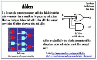
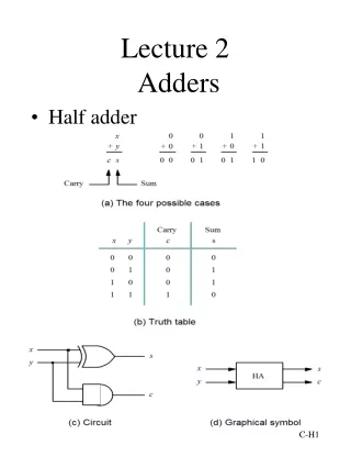
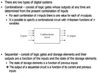
Adders • Used to perform addition, subtraction, multiplication, and division (sometimes) • Half-adder adds rightmost (least significant) bit • Full-adder adds all other bits, since a 1 may be carried into it. Use carry-out from one adder as the carry-in for the next adder • Combinational circuit (no memory)
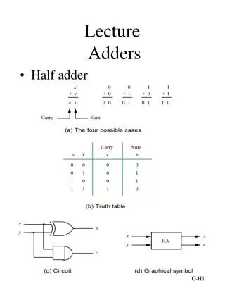
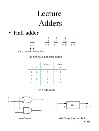
Half-Adder • A Half Adder (HA) is a 2-input, 2-output combinational circuit that adds the inputs and produces a Sum and a Carry • The Boolean expressions and the circuit for the Sum S and the carry C are given below: • Half adder • Inputs two 1-bit values, X and Y • Outputs their 2-bit sum as bits C and S • C is carry • S is the sum
Result Carry Half-Adder • Only this circuit is a Half-Adder • Other circuits may be equivalent, however
Half-Adder • How to know a circuit is equivalent to half-adder ? • Circuit is equivalent to a half-adder if both truth tables have identical output • Cannot be used if there could be a carry-in bit • So used to add least significant (rightmost) bit. • Very important circuit in computers. • Addition is very common • Half-adder is found in every computer, calculator, digital watch…
Binary Full Adder • A Full Adder (FA) is a 3-input, 2-output • combinational circuit that adds the inputs and produces a Sum and a Carry • The third input can be perceived as the carry from a previous addition • The Boolean expressions and for the Sum S and • the carry C, obtained from their K-Maps, are given below:
Multiplexer A multiplexer (MUX) is a device that accepts data from one of many input sources for transmission over a common shared line. To achieve this the MUX has several data lines and a single output along with data-select inputs, which permit digital data on any one of the inputs to be switched to the output line. The logic symbol for a 1-of-4 data selector/ multiplexer is shown below, along with its associated table. Logic symbol for 1-of-4 multiplexer
Table of Operation Note that if a binary zero appears on the data-select lines then data on input line D0 will appear on the output. Thus, data output Y is equal to D0 if and only if S1=0 and S0=0
Similarly, the data output is equal to D1, D2 and D3 for , and , respectively. Thus the total multiplexer logic expression, formed from ORing terms is
Larger MUX • Technique: use hierarchies of smaller components • Example: creating 4x1 mux from 2x1 mux • Will create a 2-level mux tree • First level takes the initial inputs • The results from the first level are fed into the second level
Hierarchy Approach • Technique • Divide the truth table into equal sections • Number of sections given by type of second-level MUX • If the second-level MUX is 2x1 then need 2 sections in the TT Section 1 Section 2
Hierarchy Approach • Technique • Connect the outputs corresponding to individual sections of the TT to the data lines of the individual first-level MUXs Input 0 Outputs from Section 1 of Truth Table 2x1 Mux Input 1 Outputs from Section 2 of Truth Table 2x1 Mux Input 2 Input 3
Hierarchy Approach • Technique • Connect the outputs of the first-level MUXs to the data lines of the second-level MUX following the order of the sections Input 0 2x1 Mux Input 1 2x1 Mux 2x1 Mux Input 2 Input 3
Hierarchy Approach • Technique • Connect the outputs of the first-level MUXs to the data lines of the second-level MUX following the order of the sections Input 0 2x1 Mux Input 1 2x1 Mux 2x1 Mux Input 2 Input 3
Decoders • A decoder: • Accepts a Boolean value (number) and activates the corresponding output line • All other lines are deactivated • For n inputs there are 2n output lines • Each possible input value corresponds to an output line
Decoders Motivation (one example) CPU needs to select channel => assign address to each device Need a way to activate device. MEMORY PRINTER COMMUNICATION CHANNEL CPU MOUSE DISPLAY
Decoders ACTIVATION LINE Motivation CPU needs to select channel => assign address to each device Need a way to activate device. MEMORY ADDRESS CODE PRINTER ADDRESS DECODER CPU MOUSE DISPLAY
A i = 0 B i = 1 1, iff A,B is 01 i = 2 1, iff A,B is 10 i = 3 1, iff A,B is 11 Decoder • An n input decoder has 2n outputs. • Outputi is 1 iff the binary value of the n-bit input is i. • At any time, exactly one output is 1, all others are 0. 1, iff A,B is 00
Decoder with Enable • In general, attach m-enabling circuits to the outputs • See truth table below for function • Note use of X’s to denote both 0 and 1 • Combination containing two X’s represent four binary combinations • Alternatively, can be viewed as distributing value of signal EN to 1 of 4 outputs • In this case, called ademultiplexer
Encoders • An encoder: • For 2n inputs there are n output lines • Outputs the Boolean value corresponding to the input line number • There is a special output line V that indicates whether any input lines are active.