Download
1 / 44
480 likes | 687 Views
The Solar Hydrogen Project. Steve Dennison and Bojan Tamburic Dr Klaus Hellgardt Prof Geoff Kelsall Prof Geoff Maitland Dept of Chemical Engineering, Imperial College, LONDON SW7 2AZ. Structure of presentation. Background Biohydrogen (Bojan Tamburic)

E N D
The Solar Hydrogen Project Steve Dennison and Bojan Tamburic Dr Klaus Hellgardt Prof Geoff Kelsall Prof Geoff Maitland Dept of Chemical Engineering, Imperial College, LONDON SW7 2AZ
Structure of presentation Background Biohydrogen (Bojan Tamburic) Photoelectrochemical Hydrogen (Steve Dennison) Questions
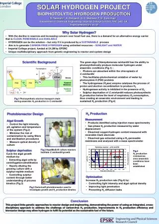
Why Hydrogen? It is a good route to storage of solar energy Key feedstock in petroleum refining Important feedstock in the chemical industry (NH3, methanol, etc.) A fuel for the future (in fuel cells) - towards the hydrogen economy?
Solar Hydrogen Project Multi-department/discipline project at Imperial (Chemistry; Biological Sciences, Chemical Engineering, Earth Sciences). £4.5M, 5-year programme investigating and developing systems for the generation of sustainable hydrogen using solar energy as the major energy input.
Hydrogen Production Today Steam reformation of methane (+ other light hydrocarbons) ~5 kg carbon dioxide is produced per kg H2 which is not sustainable!
Routes to Hydrogen Production adapted from J.A.Turner, Science 285, 687(1999)
Clean (CO2-free) Hydrogen Electrolysis (?) Photoelectrolysis Biophotolysis
Solar Hydrogen ProjectBiohydrogen Production Bojan Tamburic Prof. Geoffrey Maitland Dr. Klaus Hellgardt
1) Hydrogen production and utilisation Hydrogen as a fuel Clean and green H2 production 2) Green algal routes to solar hydrogen Photosynthetic H2 production Two stage growth and hydrogen production procedure 3) Main challenges facing biohydrogen production Growing algal biomass Inducing metabolic change Measuring and optimising H2 production 4) Early experimental results and their significance Biohydrogen lab Algal growth Batch reactor Sartorius reactor (1) Sartorius reactor (2) Future outlook Producing more H2 Automating and scaling-up Introduction
Content • Hydrogen production and utilisation • Green algal routes to solar hydrogen • Main challenges facing biohydrogen production • Early experimental results and their significance • Future outlook
Hydrogen as a fuel • Environmental concerns over: • CO2 emissions • Vehicle exhaust gasses (SOx, NOx) • Sustainability concerns: • Peak oil • Global warming • Hydrogen – transport fuel of the future • Proton exchange membrane (PEM) fuel cells use H2 to drive an electrochemical engine; the only product is water • Barriers that must be overcome: • Compression of H2 • Development of Hydrogen infrastructure • Sustainable H2 production
Clean and green H2 production • Bulk Hydrogen is typically produced by the steam reforming of Methane, followed by the gas-shift reaction: • CH4 + H2O → CO + 3H2 • CO + H2O → CO2 + H2 • Negates many of the benefits of PEM fuel cells • Renewable and sustainable H2 production required • Can be achieved by renewable electricity generation, followed by water electrolysis, but: • Low efficiency • High costs • Can use electricity directly “Photosynthetic H2 production by green algae may hold the promise of generating renewable fuel from nature’s most plentiful resources – sunlight and water” – Melis et al. (2007)
Content • Hydrogen production and utilisation • Green algal routes to solar hydrogen • Main challenges facing biohydrogen production • Early experimental results and their significance • Future outlook
Photosynthetic H2 production • Discovered by Gaffron in 1942 • Direct H2 photoproduction • 2H2O → 2H2 + O2 • Solar energy absorbed by Photosystem II and used to split water • Electrons transported by Ferredoxin • H2 production governed by the Hydrogenase enzyme – a natural catalyst • Anaerobic photosynthesis required • Process provides ATP – energy source • No toxic or polluting bi-products • Potential for value-added products derived from algal biomass Hallenbeck & Benemann (2002)
Two-stage growth and hydrogen production procedure • Hydrogenase enzyme deactivated in the presence of Oxygen – limit on volume and duration of H2 production • Two-stage process developed by Melis et al. (2000) • Grow algae in oxygen-rich conditions • Deprive algae of sulphur • Photosystem II protons cannot regenerate their genetic structure • Algae use up remaining oxygen by respiration and enter anaerobic state • Algae produce H2 and ATP • H2 production slows after about 5 days as algae begin to die • Use the model green algae C.reinhardtii Melis et al. (2002)
Content • Hydrogen production and utilisation • Green algal routes to solar hydrogen • Main challenges facing biohydrogen production • Early experimental results and their significance • Future outlook
Micro-algal cultivation units from Aqua Medic TAP growth medium, sources of light and agitation Store algal cultures after they are grown in Biology Several wild type strains of C.reinhardtii Dum24 & other mutants Algal growth can be measured by Counting number of cells (microscopy) Chlorophyll content Optical density (OD) Can we grow algae: Quickly and efficiently? To the OD required for H2 production? Without contamination? Can the growth process be scaled up? Growing algal biomass
Hydrogen production is induced by sulphur deprivation Centrifugation Typically used in Biology Culture spun-down until pellet of algal cells forms Procedure time consuming and results in loss of cells Dilution TAP-S inoculated (~10% v/v) with growing culture sample Remaining sulphur used up as algae grow; anaerobic conditions established Inefficient to ‘re-grow’ biomass Ultrafiltration Cross-flow system with backwash of algal cake Similar challenges as with centrifugation, but easier to scale-up Nutrient control Investigate algal growth kinetics Algae should run out of sulphur as they reach optimal OD Concerns over biological variations Inducing metabolic change
Measuring and optimising H2 production • Measuring H2 production • Water displacement • Injection mass spectrometry • Membrane inlet mass spectrometry (MIMS) • Optimising H2 production • Grow algae to sufficient OD • Optimise system parameters • Determine suitable nutrient mix
Content • Hydrogen production and utilisation • Green algal routes to solar hydrogen • Main challenges facing biohydrogen production • Early experimental results and their significance • Future outlook
Biohydrogen lab • Culture reactor • Measuring probes and tubing connections including: • Condenser for hydrogen collection • Thermocouple • pH, pO2 and OD sensors • MIMS system • Main vessel of the Sartorius photobioreactor (PBR) • Sartorius PBR control tower • Peristaltic pump • Water displacement system • Water-proof electric plugs • Stainless steel worktop a) b) g) c) d) e) f) h)
Algal growth • Measure optical density - correlate to chlorophyll content and cell count • Challenge is to provide adequate and stable growth conditions
Batch reactor • Test of process parameters • H2 detection by: • Water displacement • Injection mass spectrometry • H2 production was 5.2 ml/l of culture – total of 15ml over 5 days
Sartorius reactor (1) • Used dilution method of sulphur deprivation • OD rises as algae grow, then drops as algae use up starch reserves while producing H2
Sartorius reactor (2) • Hydrogen production activated upon the introduction of anaerobic photosynthesis • H2 production - 3.1±0.3 ml/l of culture
Content • Hydrogen production and utilisation • Green algal routes to solar hydrogen • Main challenges facing biohydrogen production • Early experimental results and their significance • Future outlook
Producing more H2 • Need to expand our understanding of the process • Improve photochemical efficiency or increase algal lifetime • Different algal strains • Dum24 (no cell wall) • Stm6 (genetically engineered for H2 production) • New mutants from Biology • Alternative wild type strains, marine species • Optimising process parameters • Initial optical density • Light intensity, temperature, agitation and pH • Nutrient content • Sulphur re-insertion (increasing lifetime)
Automating and scaling-up • Improve H2 measurement technique • Develop continuous S-deprivation process • Use natural light (or solar simulator) • Develop ultrafiltration system • Prolong algal lifetime by sulphur re-insertion • Cycle algal cultures and nutrients • Investigate cheaper nutrients and circulation systems • Collect produced hydrogen (membrane) • Connect to PEM fuel cell system • Ultimate aim is ~20l outdoor reactor
Solar Hydrogen ProjectPhotoelectrochemical Hydrogen Production Steve Dennison Prof. Geoff Kelsall Dr. Klaus Hellgardt
Content Background and history Energetics of the semiconductor-electrolyte interface and H2 Production Characterisation of the semiconductor-electrolyte interface Future Work
Background and History Photoelectrochemistry of semiconductors Fujishima & Honda (1972) Single crystal TiO2 Near UV light ( ~ 390-400 nm) Produced H2 and O2 from water without external bias
Energetics of the semiconductor-electrolyte interface Requirements for a photoelectrode: Thermodynamic energy for water: 1.23 eV Band bending: 0.4 eV Separation of ECB and EF: 0.3 eV Overpotential for O2: 0.4 eV Total: ~2.4 eV
Energetics of the semiconductor-electrolyte interface: possible materials Fe2O3: Eg ~ 2.2 (to 2.4) eV WO3: Eg ~ 2.6 eV Nitrogen-doped TiO2: Eg < 3.1 eV TiO2: Eg ~ 3.1 eV
Characterisation of the semiconductor-Electrolyte Interface Current-voltage response, under dark and illuminated conditions (analysis of general response) a.c. impedance, in the dark (probe of interfacial energetics: flat-band potential, dopant density) Photocurrent spectroscopy (IPCE, Incident Photon to Current Efficiency)
Fe2O3 EPD Fe2O3: As-Deposited EPD Fe2O3: Annealed Fe2O3 by Spray Pyrolysis
Fe2O3: Current-potential response Electrophoretically deposited Fe2O3
Fe2O3: Current-potential response CVD Fe2O3 (Hydrogen Solar)
Fe2O3: Photoelectrode Performance * Produced at Hydrogen Solar: FeCl3/SnCl2 (1%) in EtOH ‡ 400°C in air for 30 min.
Future Work Materials development: Evaluate further materials: TiO2; WO3; N-doped TiO2. Improvements to Fe2O3 deposition Development of fabrication techniques (CVD, cold plasma deposition) Texturing of semiconductor films Complete (high-throughput) photocurrent spectrometer and full thin-film semiconductor characterisation system Develop identification of new materials, using theoretical and empirical approaches.
Future Work Evaluation of particulate semiconductor systems and comparison with electrochemical systems. Development of a photoelectrochemical reactor(10 x 10 cm scale): design, modelling and optimisation Leading, ultimately, to a demonstrator system
Any questions? Bojan.Tamburic@imperial.ac.uk s.dennison@imperial.ac.uk