Download

1 / 15
150 likes | 235 Views
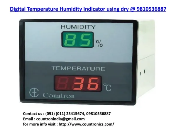
This system is designed to control a fan based on humidity levels. It utilizes an HC9S08QE32 MCU with specific memory requirements and a timeslice kernel for efficient task handling. Tasks include startup, display, humidity detection, fan control, timing, and more. The system closely monitors humidity through voltage observations and activates or deactivates the fan accordingly. The interface also includes a push-button switch for manual control. With low CPU load and precise task timing, this controller ensures optimal fan operation. Fans can be controlled automatically or manually depending on the humidity conditions.

E N D
Humidity Sensing Fan Controller Jason Huft 05/11/10
General System Requirements • MCU: HC9S08QE32, 44 pin package • Bus Frequency: approximately 50 MHz Internal clock source. • Timeslice Kernel • Timeslice Period: 100 ms • Memory Available: • 32k EEPROM • 2k RAM • Memory Requirement: • 8-10k EEProm • 2k RAM
Timeslice Kernel Tasks • Startup Task • Push-Button Task • Display Task • Humidity Detect Task • Fan Control Task • Timing Task • WaitForSlice
Start Task • Sets initial state of the system and initializes the registers. • Execution Time: • 100ms worst case. • Period: • Once at Startup
Push-Button Task • Waits and recognizes a key press on a push-button switch.De-bounces the switch. • Period: 20ms (sporatic) • Execution Time: 10μs • Changes state from key press • Off • On (can recognize multiple presses of this key) • Automatic
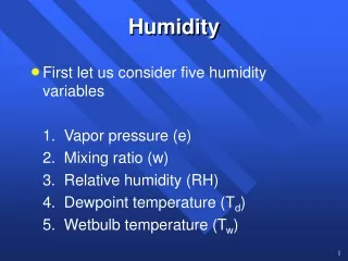
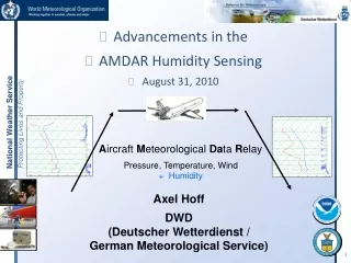
Humidity Detect Task • Observes changing voltage from the sensor • Converts the voltage into digital information • Passes voltage level as a hex output to the MCU. • Period 100ms • Execution Time 5μs
Display Task • Writes information to LCD display • Takes timing information from timer task • Also reports current state if in On or Automatic State. • Period: 100ms • Execution Time: about 5ms.
Fan Control Task • Interrupts information from the Humidity Detect Task to choose if the fan should be on/off in automatic state. • Calls fan activated/deactivate based on state. • Period: 20ms (sporadic) • Execution Time: 20us max (10 us average)
Timing Task • Keeps track of remaining time in the on state. • Mostly internal clock. Receives information from Push-Button Task • Changes system state if certain conditions are met. • Period: 100ms • Execution Time: 20us or so
Wait for Slice • Fills the remaining time in each slice period. • Included to assist in proper task timing and debugging. • Period: 100ms • Execution Time: Varies based on how many other tasks need to execute in one slice period.
CPU Load • Max CPU Load • 20us/100ms + 20us/20ms + 5ms/20ms + 10us/20ms + 5us/100ms = .05175 * 100 = 25.175% Max CPU load - 20us/100ms + 5ms/100ms + 10us/20ms + 5us/100ms = 5.12% average CPU Load
AtD Converter Dataflow Diagram Humidity Detect Task A\D Converter A-to–D I/O pin Ts = 100ms ADCCFG AtDInit() AD0 ADP0 ADCSC1 HumidityRead() HumidityLevel