Download

1 / 55

E N D
LHC Inner Triplet Status J . Kerby For…Ranko Ostojic, Cedric Garion, Tom Page, Thierry Renaglia, Herve Prin, Bob Wands, Frederic Gicquel, Ingrid Fang, Juan Carlos Perez, Tom Nicol, Sandor Feher, Tatsu Nakamoto, Peter Limon, Joseph Rasson, Steve Virostek, Paul Olderr, Tom Peterson, Jim Strait, Jim Rife, Vadim Kashikin…and anyone else I have inadvertently forgotten…
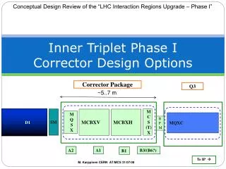
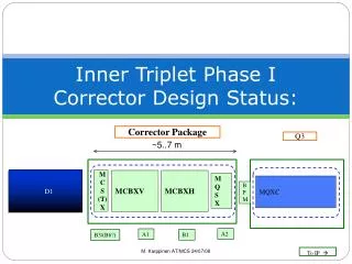
Review of 27 March sector 7-8 pressure test • Requirements for the fix • Cartridge for Q1 / Q3 • Vacuum Loading • DFBX • Schedule 14 June 2007
Non IP end of Q1, looking toward IP The Xb, XBt, V EE and FF lines, and beam screen lines were not pressurized during the 27 Mar test 14 June 2007
Tables for the full load case when all lines are pressurized to MAWP • 27 March test the pumping and shield lines were not pressurized, and failure was at 20 bar • Q1 load 115kN • Q3 load 93kN 14 June 2007
Q3 94kN Q1 115kN 14 June 2007
Cold Mass Support • A ‘fixed’ and ‘free’ spider support • Invar rod connecting the two to share support 14 June 2007
Geometry was drawn directly from the CAD model. The bellows at the interconnections between cold masses were simulated with spring elements having a total stiffness of 5500 lbs/in at each interconnection. Moments due to the L line bellows were estimated, and are reacted w/ much longer lever arm of the spacing of the supports, so are a small effect in these analyses. Elements are second-order hexahedral and tetrahedral solids. A total of 500 thousand elements and 600000 nodes were used. 14 June 2007
Meshing of the supports was refined to include three elements through the half-inch thickness of the G11. The G11 was treated as orthotropic; in the plane of the support (the xy plane in the analysis) bending is resisted primarily by the tension or compression of the relatively stiff glass fibers; the Young's modulus is dominated by the glass, and was set to 3e6 psi in both the x and y directions. For the z-direction (through the thickness), loads are perpendicular to the glass fibers, and the stiffness is influenced more strongly by the epoxy matrix; a reduced modulus of 1e6 psi was used for this direction. Note that while this is technically "orthotropic", it really assumes isotropy in the xy plane. 14 June 2007
IP IP bellows - 1920 lbs 30700 lbs Q1 sliding support - 8760 lbs fixed support - 20100 lbs bellows - 1654 lbs bellows – 1920 lbs Q2 sliding support - 65 lbs fixed support - 150 lbs sliding support - 55 lbs Q1- Q2 - full 20 bar load (all lines) 14 June 2007
IP 25800 lbs bellows - 1654 lbs Q3 sliding support - 7330 lbs fixed support - 16900 lbs Q3 – full 20 bar load (all lines) 14 June 2007
Pressure Test Summary • With Shield and Xb lines empty, actual loads 84% of 20 bar load in model…results linearly scaled for now: • Q1 fixed support failed at 16,950lbs/75.4kN (7.5mm); then propagated to Q1 free support • Q3 fixed support being checked at 14250lbs/63.3kN (6.4mm); Q3 free support shows no signs of damage • Q2 unaffected • DFBX damage not from interaction with Q3 14 June 2007
Requirements for a Fix • In Situ • Does not move fixed point of the assemblies • React loads with sufficient stiffness to limit deflection – ~140kN design load (slide 4) • Acts at any temperature 300K to 2K • Focus on implementation in Q1—Q3 solution identical in length, IP end 14 June 2007
Fixed Points Internal heat exchanger FP Cold Mass-Vacuum Vessel Fixed Point HX-Cold Mass External heat exchanger (HX) D1 Q3 Q2B Q2A Q1 DFBX MQXA MQXB MQXB MQXB MQXA LBX Fixed Point Triplet-Tunnel Floor Tie Rods Linking Vacuum Vessels Jacks (longitudinal) 38490 14 June 2007
Q1 14 June 2007
Q1 Corrector Containment MQXA 14 June 2007
Q3 14 June 2007
Q3 Corrector Containment MQXA 14 June 2007
Allowable Deflection of Support • From failure analysis support fails at deflection of 7.5mm (6.4mm borderline) • System Analysis from Q1-Q2-Q3 • Cooldown deflection ~1.0mm in Q2 free spiders (all tested, ok) • Analysis of test in fixture, test results, suggest 2.8mm 14 June 2007
IP IP bellows - 7940 lbs (6000 lbs) 30700 lbs (0 lbs) Q1 sliding support - 5560 lbs (-3190 lbs) fixed support - 17220 lbs (-2840 lbs) bellows - 7770 lbs (6115 lbs) bellows – 7940 lbs (6000 lbs) Q2 sliding support - 2260 lbs (2195 lbs) fixed support - 60 lbs (-86 lbs) sliding support - 2250 lbs (2300 lbs) Cooldown / 20 bar loads – Q1/Q2 35kN (27kN) 137kN (0kN) 25kN (-14kN) 77kN (-13kN) 35kN (27kN) 35kN (27kN) 10kN (10kN) 10kN (10kN) 0kN (0kN) 14 June 2007
IP 25800 lbs (0 lbs) bellows - 7770 lbs (6115 lbs) Q3 sliding support - 4140 lbs (-3230 lbs) fixed support - 14030 lbs (-2826 lbs) Cooldown / 20 bar loads – Q3 • Contraction of cold mass interconnect bellows Q1-Q2 and Q2-Q3 reacts portion of quench load • Further models move from full triplet to Q1 only w/ load of interconnect bellows included • W/ cooldown, free support pulled toward fixed support by Invar tie rod 115kN (0kN) 35kN (27kN) 18kN (-14kN) 62kN (-13kN) 14 June 2007
Allowable Deflection of Support • Testing / modeling to failure of individual supports • The cold mass provides a rotational constraint on the support and lug which does not exist in the test fixture • Test of single spider in fixture failed at 6900lbs, 17mm deflection • Modeling used to translate results to spider / invar system, including gravity loads. • 2.8mm bending of spider in installed configuration OK including safety factors • Removing front split ring on fixed support adds another 17.5mm of allowable motion 14 June 2007
Removing the front split ring is important as the cartridge is a much stronger spring than the support and would pull the cold mass 5.5mm if a large thermal mismatch existed Addition of 17.5mm of travel by removing this split ring, and using the cartridge to set the fix point of the assembly, greatly simplifies failure mode analysis. 14 June 2007
Cartouche / Cartridge • Affixed at Q1 non-IP end; Q3 IP end • Transfer load at all temperatures • Limits support deflections 14 June 2007
Figure 1. Finite Element Model of Q1 with Cartridge Q1 Cartridge Modeling • Cartridge applied to Q1 model including bellows for: • Warm 25 bar pressure test load • Cold • Cold, 20 bar quench load 14 June 2007
IP bellows - 360 lbs 38400 lbs Q1 Figure 2. Forces on Components due to 25 Bar Warm Pressure Test Load cartridge - 32300 lbs sliding support - 1720 lbs fixed support - 3990 lbs Q1 Cartridge, 25 bar pressure test 2kN 171kN 144kN 18kN 8kN 14 June 2007
IP Figure 3. Forces on Components due to Cooldown bellows - 6050 lbs 0 lbs Q1 cartridge - 1210 lbs sliding support - 2830 lbs fixed support - 2000 lbs Q1 Cartridge, Cooldown 27kN 0kN 5kN 13kN 9kN 14 June 2007
IP Figure 4. Forces on Components due to Cooldown and 20 Bar Pressure Load bellows - 6340 lbs 30700 lbs Q1 cartridge - 24600 lbs sliding support - 1460 lbs fixed support - 1190 lbs Q1 Cartridge, cooldown + 20 bar 28kN 137kN 109kN 5kN 6kN 14 June 2007
Q1 Cartridge, Deflections • Load per cartridge: 36kN (warm test, 25 bar evenly split) • Al tube stress (3300 psi / 8600 psi ASME allowable) (22.7MPa/59MPa allowable) • Invar peak cross section (16600 psi / 21600 psi) (114MPa / 148MPa) (Allowable – 3 to ultimate or 2 to yield of annealed Invar) 14 June 2007
Thermal Analysis 14 June 2007
Invar rod temperature 14 June 2007
Vacuum vessel flange temperature 14 June 2007
Cartridge Summary Cartridge design in production and testing • Worst case Q1 spider support longitudinal deflection < 2mm limit • Worst case Q1 spider load < ¼ load that caused failure during recent pressure test • Does not move magnet fix point • In fact fixes Q1 / Q3 better than currently • Magnetic effect negligible • Additional load to 2K of a few Watts; Vacuum Oring OK. • Mechanical tests have been done on: • Removal of split ring at fixed point • Invar / Al tube connection • Vacuum bracket to flange weld • Full standalone cartridges • Test of 4 cartridges installed on a Q1 in process, actual test next week • Successful removal of split ring covers upset conditions • Covers failure modes in thermalization of cartridge / cold mass • On track for sector 8-1…. 14 June 2007
Q1 14 June 2007
Q1 14 June 2007
Vacuum Loads to Ground 14 June 2007
Vacuum vessel to ground • Apr 24-25 Review noted issues to be resolved w/ alignment / jacks / tunnel ground under triplets • Safety factor of vacuum tie bars between vacuum vessels and DFBX also questioned 14 June 2007
38400 lbs tot rod force = 22600 lbs IP V1 bellows force = 500 lbs tot rod force = 22600 lbs tot rod force = 22600 lbs IP V2 bellows force = 500 lbs bellows force = 500 lbs 30300 lbs tot rod force = 7100 lbs tot rod force = 22600 lbs V3 IP bellows force = 100 lbs bellows force = 500 lbs 25 bar load + Vacuum load (+bellows); no transverse load on jacks 171kN • Vacuum Vessel Deflections • V1 4.3mm to IP • V2 2.0mm to IP • V3 0.4mm from IP • Vac Bellows makes ~5% change in deflections in 2 previous cases 100kN 2kN 100kN 100kN 2kN 2kN 135kN 100kN 32kN 14 June 2007 1kN 2kN
Vacuum Tie Bar Ass’y Outer nut omitted to prevent excessive load in the event of a cryogen spill inside the vacuum vessel 14 June 2007
Connection Details Nut to tighten sleeve against intermediate ear Nut to tighten assembly against vacuum vessel ear 2” OD, 1.25” ID sleeve Tie rod, nuts, and spherical washers are the same as those in the current system Spherical washers Tie rod 14 June 2007
Connections Details (2) 14 June 2007
DFBX 14 June 2007
DFBX-E 17 Feb 05 14 June 2007
Bus Duct Assembly: Thrust Load D1: 10.1 KN LD: 6.5 KN Q3: 20 KN Thrust Support Brackets 14 June 2007