Download
1 / 18
430 likes | 1.7k Views
Fundamentals of Descriptive Geometry. AT 301 Dr. Trent. Introduction. Most of the concepts of this chapter have already been touched on in prior lectures and exercises. The intent of this lecture to provide another view of the principles and concepts from an analytical standpoint.

E N D
Fundamentals of Descriptive Geometry AT 301 Dr. Trent
Introduction • Most of the concepts of this chapter have already been touched on in prior lectures and exercises. • The intent of this lecture to provide another view of the principles and concepts from an analytical standpoint.
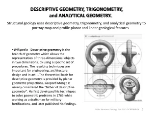
Descriptive Geometry • Descriptive geometry is the graphic representation of plane, solid, and analytical geometry used to describe real or imagined technical devices and objects. • It is the science of graphic representation in engineering design. • Students of technical or engineering graphics need to study plane, solid, analytical, and descriptive geometry because it forms the foundation or grammar of technical drawings.
Uses of Descriptive Geometry • Descriptive geometry principles are used to describe any problem that has spatial aspects to it. • For example the application of descriptive geometry is used in: • The design of chemical plants. For the plant to function safely, pipes must be placed to intersect correctly, and to clear each other by a specified distance, and they must correctly intersect the walls of the buildings. • The design of buildings • The design of road systems • The design of mechanical systems
Methods of Descriptive Geometry • There are three basic methods • Direct View • Fold Line • Revolution • The differences is in how information is transferred to adjacent views.
Direct View Method • Reference plane is used to transfer depth info between related views. • Length information comes by projection lines from the adjacent view.
Fold-Line Method • A variation on the Direct View method. • The reference line is moved between the views to represent the folds in a glass box.
Revolution Method • The projectors from the adjacent view are not parallel to the viewing direction (as related to the object) • Need to rotate the length information about an axis before projecting it to the new adjacent view.
Reference Planes • The reference plane is perpendicular to the line of sight project lines. It appears as a line in related views. • Gives a reference for measuring depth information for related views.
Basic Elements • The basic elements used in descriptive geometry include: • Points • Lines • Planes • Coordinate systems are mathematical tools useful in describing spatial information • Cartesian coordinate systems are the most commonly used.
Cartesian Coordinate System • Points are located relative to the origin of the coordinate system.
Points • A point has no width, height, or depth. • A point represents a specific position in space as well as the end view of a line or the intersection of two lines. • The graphical representation of a point is a small symmetrical cross.
Lines • Lines represents the locus of points that are directly between two points. • A line is a geometric primitive that has no thickness, only length and direction. • A line can graphically represent the intersection of two surfaces, the edge view of a surface, or the limiting element of a surface. • Lines are either vertical, horizontal, or inclined. A vertical line is defined as a line that is perpendicular to the plane of the earth (horizontal plane).
True Length Lines • A true length line is the actual straight-line distance between two points. • In orthographic projection, a true-length line must be parallel to a projection plane in an adjacent view.
True Length Lines • True length lines are ALWAYS parallel to the reference plane in ALL adjacent views. • To find the true length of a line, draw a view of the line where the reference plane is parallel to an adjacent view of the line.
Principles of Descriptive Geometry Rule #1 If a line is positioned parallel to a projection plane and the line of sight is perpendicular to that projection plane, then the line will appear as true length