Download
1 / 12
120 likes | 244 Views
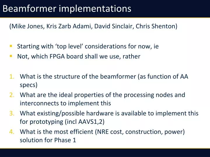
Beamformer implementations. (Mike Jones, Kris Zarb Adami , David Sinclair, Chris Shenton ) Starting with ‘top level’ considerations for now, ie Not, which FPGA board shall we use, rather What is the structure of the beamformer (as function of AA specs)

E N D
Beamformer implementations (Mike Jones, Kris ZarbAdami, David Sinclair, Chris Shenton) • Starting with ‘top level’ considerations for now, ie • Not, which FPGA board shall we use, rather • What is the structure of the beamformer (as function of AA specs) • What are the ideal properties of the processing nodes and interconnects to implement this • What existing/possible hardware is available to implement this for prototyping (incl AAVS1,2) • What is the most efficient (NRE cost, construction, power) solution for Phase 1
Assumptions: Partial rather than heirarchicalbeamforming, ie no well-formed tile beams. • Advantages: • Better station beam quality (egDulwich et al, Limelette conference 2009) • More flexible (arbitrary station beam pointing directions) • Easy beams/bandwidth tradeoff • Disadvantages • Doesn’t reduce data rate like heirarchicalbeamformer • Can increase data rate through first part of beamformer, depending on NtilevsNbeam Separate out antenna processor • Always have to do channelization per antenna • ADC -> digital signal tranport interface – may as well have channelisation in same chip • Allows flexibility of placement of ADC
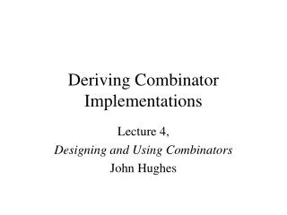
The aperture illumination problem Partial beamform Heirarchical (Tiled) beamform f A
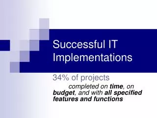
Antenna processor Digital out (antenna to bunker or local rack) ADC Channelize Data format and physical interface ADC Channelize Analogue in (local to antenna or RFoF) Timing data in Clock • Can be developed as block (almost) independently of architecture • Processing load ‘only’ ~500 GMAC/s – smallish chip compared to beamformer • SKA.TEL.LFAA.RCV.DNA, SKA.TEL.LFAA.RCV.DCH, SKA.TEL.LFAA.SP.FB
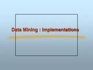
Beamformer node • In partial beamformer, only one level of coefficient multiplication • Everything else is just adders! • Implement b = M.v in blocks – each block is a ‘tile’ • Ideal implementation (simplest connections) is node with Nin = no elements in tile, Nout = no of beams (average over bandwidth) Multiplier node Coefficient matrix in M.v + Adder node
Multiplier node properties • Roughly equal worry is processing and I/O • Amount of each is large and depends strongly on station properties – no of elements and no of beams. • Internal switching needs to assemble data vectors flexibly from input antenna streams – this is only flexibility you need! • Assuming each antenna data stream = 1 GS/s 4+4 bits = 8 Gb/s encoded on a 13 Gb/s serial interface • If nbeams = 300 , Nant(tile) = 100 • Node needs 400 x 13 Gb/s interfaces and 300 x 100 x 1G = 30 TMAC/s • If nbeams = 35 (possible with dual-band array) • Node needs 135 x 6 Gb/s interfaces and 35 x 100 x 0.5G = 1.7 TMACS
Adder node • All coefficients applied in multiplier node • Adders ‘just’ add… • Ideally structured so input BW proportional to Ntiles, output BW proportional to Nbeams • Eg in 300-beams, 100-tiles, 1GS/s: • Needs 400 13 Gb/s interfaces, 77 TADD/s (assuming binary adder tree – not the most efficient) • 35-beams, 100-tiles, 0.5 GS/s: • Needs 135 6 Gb/s interfaces, 4.5 TADD/s
Current tasks Antenna processor: • Looking at filter bank specs and algorithms (SKA.TEL.LFAA.SP.FB T1-6) • Physical configuration of antenna processor in the near-antenna case (SKA.TEL.LFAA.RCV.DNA T1, T4, T9) Beamformer: • Developing parametric model of beamformer dependent on station/array parameters (SKA.TEL.LFAA.SP T4) • Investigate partition of processing architectures for different available technologies (SKA.TEL.LFAA.SP T5) • Study realisation of beamforming architectures (SKA.TEL.LFAA.SP.ARC T2) • Simulate beamformer using implementation-agnostic tools (SKA.TEL.LFAA.SP.DBF T4)