Download

1 / 32
320 likes | 466 Views
CROSSWELL IMAGING BY 2-D PRESTACK WAVEPATH MIGRATION. H. Sun. Geology and Geophysics Department University of Utah. SEG 2-D Overthrust Data. KM Image. Model. WM Image. 4. Offset (km). 10. 4. Offset (km). 10. 4. Offset (km). 10. 0.5. Depth (km). 2.5.

E N D
CROSSWELL IMAGING BY 2-D PRESTACK WAVEPATH MIGRATION H. Sun Geology and Geophysics Department University of Utah
SEG 2-D Overthrust Data KM Image Model WM Image 4 Offset (km) 10 4 Offset (km) 10 4 Offset (km) 10 0.5 Depth (km) 2.5
KM Image (Zoom A) WM Image (Zoom A) 2-D Husky Field Data 2.5 Offset (km) 5.5 2.5 Offset (km) 5.5 2.5 2.5 Depth (km) Depth (km) 5.0 5.0
SEG 3-D Salt Data KM WM CPU: 1 CPU: 1/33 Sub WM Model CPU: 1/170 Horizontal Slice (Depth=1.4 km)
A B C 2-D KM of a Single Trace C B A R S
A B C 2-D WM of a Single Trace C B A R S
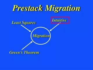
True Reflection point Small Migration Aperture Fewer Artifacts Less Expensive Wavepath Migration Traveltime + Ray Direction
Outline • WM Crosswell Imaging • Synthetic Crosswell Data • McElroy Crosswell Data • Synthetic Single Well Data • Conclusions
Interface 2 KM Crosswell Imaging Source Well Receiver Well Down-going Interface 1 Up-going
Interface 2 KM Crosswell Imaging Source Well Receiver Well Interface 1 Up-going
Interface 2 KM Crosswell Imaging Source Well Receiver Well Down-going Interface 1
Interface 2 KM Crosswell Imaging Source Well Receiver Well Down-going Interface 1 Up-going
Problems in KM Crosswell Imaging • Insufficient Stacking Leads to Artifacts • Complex Data Cause Difficulty in • Up-going and Down-going Separation • Slow Computation
Interface 2 WM Crosswell Imaging Source Well Receiver Well Down-going Interface 1 Up-going
Advantages of WM Crosswell Imaging • Avoid Artifacts by Migrating to the • Primary Reflection Point • Handle Complex Data by Migrating • Up-going and Down-going together • No Constraints Needed • Fast Computation
Shortcomings of WM • Weaker Events • Worse Interface Continuity
Outline • WM Crosswell Imaging • Synthetic Crosswell Data • McElroy Crosswell Data • Synthetic Single Well Data • Conclusions
Fault Model A Common Shot Gather Offset (m) 0 Geophone Depth (m) 0 90 210 0 0 Time (s) Depth (m) 210 0.2
Better Image Better Resolution Crosswell Imaging of Synthetic Fault Data KM Model WM WM (no separation) Offset: 0~90 m, Depth: 0~210 m
Outline • WM Crosswell Imaging • Synthetic Crosswell Data • McElroy Crosswell Data • Synthetic Single Well Data • Conclusions
Traveltime Tomogram A Common Shot Gather Offset (m) 811 Hydrophone Depth (m) 0 56 963 811 0 6.7 Time (s) Depth (m) (km /s) 4.7 0.05 963
KM Image ? ? 0 Offset (m) 56 Source Well Receiver Well 811 Up-going Depth (m) Separation Down-going 963 Synthetic Synthetic
WM Image 0 Offset (m) 56 Source Well Receiver Well 811 Up-going Depth (m) Separation Down-going 963 Synthetic Synthetic
WM Image Source Well Receiver Well 811 Up-going Depth (m) NO Separation Down-going 963 Synthetic 0 Offset (m) 56 Synthetic
Receiver Well Source Well Synthetic Synthetic KM(CPU=2.5) WM (up+down) WM(CPU=1) Offset: 0~56 m, Depth: 811~963 m
Outline • WM Crosswell Imaging • Synthetic Crosswell Data • McElroy Crosswell Data • Synthetic Single Well Data • Conclusions
OYO Salt Model Offset (km) 0 9 0 Well ? ? ? ? Depth (km) Salt ? ? ? ? 6 4.5 2.8 Velocity (km/s)
? ? ? ? OYO Salt Model Velocity Model WM image KM image 2 Depth (km) Well ????? 5 Offset (km) Offset (km) Offset (km) 2.5 6.5 2.5 6.5 2.5 6.5
Conclusions • Crosswell Synthetic Data • Fewer migration artifacts • Slightly better image resolution • Better for dipping fault boundary • No up- and down-going separation
Conclusions • Crosswell McElroy Data • Similar image quality • No up- and down-going separation • 2.5 times faster than KM • Worse image continuity • Structure details? Artificial events?
Conclusions • Single Well Synthetic Data • Similar image quality • Fewer migration artifacts
Acknowledgements I thank UTAM sponsors for their financial support