Download
1 / 21
220 likes | 252 Views
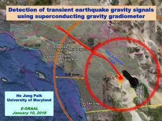
Explore the potential of detecting transient earthquake gravity signals using advanced Superconducting Gravity Gradiometer technology to reduce blind zones, improve early warning systems, and enhance seismic monitoring capabilities.

E N D
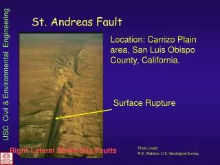
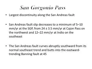
P-Wave S-Wave S-P time Detection of transient earthquake gravity signals using superconducting gravity gradiometer San Andreas Fault Ho Jung PaikUniversity of MarylandE-GRAALJanuary 10, 2018
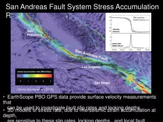
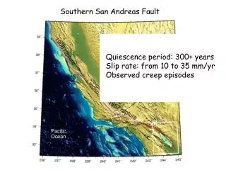
Blind zones of EEWS US West Coast earthquake hazard Blind zone size in California (Kuyuk and Allen, 2013) To reduce the blind zone, can we use gravity signals that travel at c, 105 times faster than seismic waves? Paik
Gravity signals from Tohoku earthquake From presentation by P. Ampuero (Caltech Seismolab) GRACE and GOCE missions have measured static gravity changes after vs before large earthquakes. Can dynamic gravity signals following fault rupture be measured quickly? Paik
GG signals from Tohoku earthquake hyy hzz hxx hxy hyz hzx Courtesy of J. Harms Paik
Expected dynamic gravity signal Ampuero et al., Prompt detection of fault rupture for earthquake early warning (preprint) SNR after 5 s Gravity signal following a rupture Epicentral distance = 70 km Next stage: h = 1015 Hz1/2, MANGO: h = 1020Hz1/2 SNR after 10 s Paik
Gravity gradients • To measure gravity, field on two or more masses must be differenced. • Gravity gradient ij is a symmetric 3 3 tensor: 5 independent components ii : “inline-component” ij (ji): “cross-component” Paik
Superconducting accelerometer • Low noise: • Stable scale factors Sensitive differential measurement possible. Paik
Superconducting Gravity Gradiometer (SGG) • Low noise: • I2/I1 are adjusted to balance out CM. Stable CM rejection > 107. Paik
Model 2 SGG • Sensitive SGGs have been under development for over 30 years at UM. Moody et al., RSI 73, 3957 (2002) • Test masses are mechanically suspended (fDM ~ 10 Hz). • CM platform vibration noise is rejectedto 3 parts in 108. Paik
Performance of Model 2 SGG Gravity gradient noise PSD 0.02 E Hz-1/2 103 times more sensitive than GWR gravimeter 10-12 gE Hz-1/2 By early 1990’s, SGG achieved sensitivity 103 times better than atom interferometers to date. Paik 10
Demonstration of Model 2 SGG http://www.physics.umd.edu/GRE/SGG_video.htm Paik
Tensor SGG with levitated test masses • More sensitive SGG is under development with NASA support. • Test masses are magnetically suspend (fDM ~ 0.01 Hz). 102-103 times higher sensitivity Test masses (100 g each) are levitated by a current induced along a tube. Six test masses mounted a cube form a tensor gradiometer. Paik
Demonstration of levitated SGG • Two-component SGG with levitated test masses has been demonstrated. Levitation Frequency tuning Common-mode balance Griggs et al., Phys. Rev. Applied, 064024 (2017) Paik
SGG for planetary science mission • Tensor SGG with sensitivity 2 x 10⁴ E Hz1/2 over 0.1 ~ 100 mHz. • SGG could be tuned during the mission to yield higher sensitivity at low frequencies where time-variable gravity signals are. • Cryocooler will permit 5-10 year mission lifetime. Instrument noise spectral density Creare two-stage turbo-Brayton cryocooler Paik
+ polarization x polarization SOGRO (Superconducting Omni-directional Gravitational Radiation Observatory) • Each test mass has 3 DOF. • Combining six test masses, tensor GW detector is formed. • Source direction (, ) and wave polarization (h+, h) can be determined by a single antenna. “Spherical” Antenna Paik et al., Class. Quantum Gravity 33, 075003 (2016) Paik
Astrophysics with SOGRO • SOGRO would fill0.1-10 Hzfrequency gap between the terrestrial and future space interferometers. • aSOGRO would be able to detect stellar mass BH binaries like GW150914 and alert interferometers days before merger. • SOGRO could detect IMBH binaries with 103-104M◉ at a few billion light years away, and WD binaries within the Local Group. Paik
EEW instrumentation options Two-axis Full Tensor • More information can be obtained but too large a cryostat is required. • Verticalaccelerometers are noisier due to higher resonance frequency. • By suspending as a pendulum, the platform is isolated from ground tilt. xz and yz can be measured from horizontal motions of two test masses only. Paik
SEED(Superconducting Earthquake Early Detector) • For higher sensitivity, test masses are cooled to 1.5 K and coupled to a two-stage SQUID (120 noise) via capacitor bridge transducer. Two Nb test masses weighing M = 10 kg each are separated by L = 50 cm along z axis. SEED measures xz and yz with high sensitivity, and zzand gz with 10 times lower sensitivity. Paik
Expected sensitivity of SEED at 70 km QD SQUID 120 SQUID To reject the seismic noise to below the intrinsic noise, CMRR = 109is achieved. Paik
Detection range of SEED and SOGRO SEED has a range of 50 km for M6 earthquake. SOGRO has a range of 350 km for M6 earthquake. Paik
Deployment of SEED SEED requires improvement in sensitivity by a factor of 200 beyond the SGG under development. A factor of 40comes from scaling up and a factor of 5from using alower noise SQUID. It is highly desirable to use cryocoolers to cool and operate SEEDs. Pulse-tube cryocoolers are not quiet enough. Vibration-free 4-Kturbo-Brayton cryocoolers are under development. To cover the West Coast of the United States, a few 10s of SEEDs,one sensor every ~50 km near major faults may be required. We need to perform a systematic cost-benefit analysis of SEED in comparison with conventional EEWS. Paik