Download
1 / 20
210 likes | 326 Views
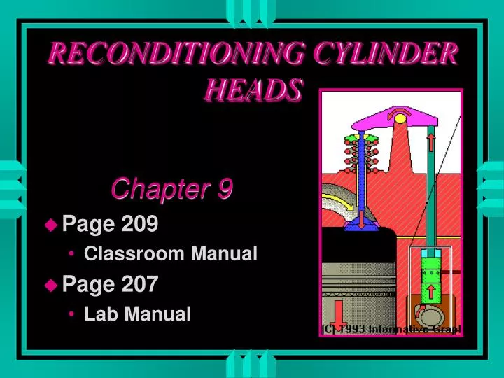
RECONDITIONING CYLINDER HEADS. Chapter 9 Page 209 Classroom Manual Page 207 Lab Manual. CHAPTER OBJECTIVE. Correct valve guide clearance by: Knurling. Reaming to accept oversize valve stems. Installing bronze guide liners. Installing cast iron guide inserts.

E N D
RECONDITIONING CYLINDER HEADS Chapter 9 • Page 209 • Classroom Manual • Page 207 • Lab Manual
CHAPTER OBJECTIVE • Correct valve guide clearance by: • Knurling. • Reaming to accept oversize valve stems. • Installing bronze guide liners. • Installing cast iron guide inserts. • Replace intregal and insert valve seats. • Grind valve seats & correct contact pattern.
CHAPTER OBJECTIVE • Recondition valve faces & tips. • Identify proper valve face-to-seat contact pattern. • Correct valve stem seal allignment. • Replace worn or damaged pressed-in rocker arm studs with oversize and threaded studs. • Resurface cylinder head sealing surface.
CHAPTER OBJECTIVE • Measure & correct valve guide height. • Measure & correct valve spring installed height. • Measure & correct valve stem height.
VALVES and VALVE SERVICE • Exhaust Seat temperature 800 degrees • Exhaust Valve neck temperature 1300 degrees • Depend on seat contact for cooling
Effect of Valve Lash on Cooling • Tight valves will not allow proper seating • Resulting in a burned valve
UNLEADED GAS • Valve seat wear • Loss of valve lash
Temperature Protection • Positive valve rotators • Rotators can cause excessive valve face wear • Multi-Groove keepers allow passive rotation • Check Multi-Groove valves for wear • Sodium filled valves • Page 165
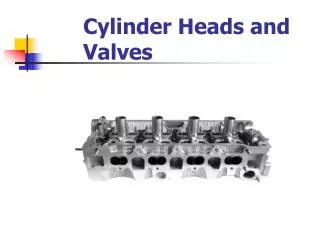
Exhaust and Intake Valves • Exhaust valves are smaller • Intake valves are larger • Valve stem tips are hardened
MEASURING the VALVE STEM • .001 MAXIMUM WEAR
STEM WEAR • Rocker arm side force on the valve stem causes valve stem and valve guide wear. • Figure 9-15 Page 217 Classroom Manual
OIL CONSUMPTION • Figure 9-16 Page 218 Classroom Manual
GUIDE PROTRUSION • Figure 9-19 Page 221 Classroom Manual
BEVELING GUIDE • Figure 9-25 Page 224 Classroom Manual
SEAT ANGLES • Figure 9-26 Page 224 Classroom Manual
VALVE SEAT GRINDING Page 227
VALVE SEAT GRINDING • Figure 9-33 Page 228
BEFORE TOPPING • Figure 9-36 Page 229
AFTER TOPPING • Figure 9-36 Page 229