Download
1 / 20
210 likes | 528 Views
CTL - redundancy. Saman, Slimane, Gary, Rajat Last Updated : June 11, 2010. Section – I Reference Memory Description provided by Gary - used in the definition of each proposal. Memory Architecture 8224 words, 14 bits, mux 16. Rows 512 and 513. 2 Spare rows (Top Bank).

E N D
CTL - redundancy Saman, Slimane, Gary, Rajat Last Updated : June 11, 2010
Section – IReference Memory Descriptionprovided by Gary - used in the definition of each proposal
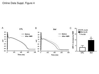
Memory Architecture8224 words, 14 bits, mux 16 Rows 512 and 513 2 Spare rows (Top Bank) 2 Spare rows (Bottom Bank) Rows 0 thru 511 Bit 0 Bit 6 Bit 7 Bit 14 1 group of 8 spare columns (left half) 1 group of 8 spare columns (right half)
Spare Elements • Any spare row in bottom bank can repair any row in the bottom bank • Any spare row in the top bank can repair either of the rows (only 2) in the top bank • Any group of 8 columns in left array can be repaired • Any group of 8 columns in the right array can be repaired
Section – IICTL Syntaxlists all proposals and resolution on each
CTL Environment Signals { “Q”[13..0] Out; “A”[13..0] In;“D”[13..0] In; “CRE1” In; “FBA1” [3..0] In “CRE2” In; “FBA2” [3..0] In “RRE1” In “FRA1”[8..0] In “RRE2” In; “FRA2”[8..0] In; “RRE3” In; “FRA3” In; “RRE4” In; “FRA4” In } Environment “myStrangeMemory” { CTL { CRE1 { DataType RepairEnable {ActiveState ForceUp;}} FBA1[3] { DataType RepairAddress;} FBA1[2..0] {DataType RepairDataBit; { ValueRange 0 6; } } CRE2 { DataType RepairEnable {ActiveState ForceUp;}} FBA2[3] { DataType RepairAddress;} FBA2[2..0] {DataType RepairDataBit; { ValueRange 0 6; }} RRE1 {DataType RepairEnable {ActiveState ForceUp;}} FRA1[8..0] {DataType RepairAddress;} RRE2 {DataType RepairEnable {ActiveState ForceUp;}} FRA2[8..0] {DataType RepairAddress;} RRE3 {DataType RepairEnable {ActiveState ForceUp;}} FRA3 {DataType RepairAddress;} RRE4 {DataType RepairEnable {ActiveState ForceUp;}} FRA4 {DataType RepairAddress;} }
CTL – Memory Repair (1) MemoryProperties { SimultaneousReadWrite None; ColumnMultiplexing 16; TopologicalOrg Adjacent; } MemoryRepair{ RepairResource Column1 { RepairType Column; AccessSignals ‘CRE1 + FBA1[3..0]’ Width 8 AddressMap xxxxxxxxxxrxxx DataBitMap 0rrr | DataBitMap xxxxxxx_rrrrrrr } RepairResource Column2 { RepairType Column; AccessSignals ‘CRE2 + FBA2[3..0]’ Width 8 AddressMap xxxxxxxxxxrxxx DataBitMap 1rrr } • Uses the traditional map vector 0|1|r|x • Uses ValueRange to restrict the bits range • Advantage • bit to bit mapping according to the data/address range • Limitations • When data are large possible confusion • The above notation cannot describe if multiple repair resources map to unequal segments of a memory. for e.g. the following memory cannot be described • two redundant columns in a 128 column memory, where first redundant column can repair any one of first 32 columns and the second can repair an of 33-127th column. • status : discarded
CTL – Memory Repair (2) MemoryProperties { SimultaneousReadWrite None; ColumnMultiplexing 16; TopologicalOrg Adjacent; } MemoryRepair{ RepairResource Column1 { RepairType Column; AccessSignals ‘CRE1 + FBA1[3..0]’ Width 8 ColumnAddressMap [15..0] | [3] /* map the column address only */ DataMap [6..0] } RepairResource Column2 { RepairType Column; AccessSignals ‘CRE2 + FBA2[3..0]’ Width 8 ColumnAddressMap [15..0] | [3] DataMap [13..7] } • does not rely on ValueRange • use an interval format [TopRange..BottomRange] • Limitations • Repair resource width > 1 issue • Cannot effectively describe restrictions on the repair resource on repair of set of ‘n’ columns • Status : discarded
CTL – Memory Repair (3) MemoryProperties { SimultaneousReadWrite None; ColumnMultiplexing 16; TopologicalOrg Adjacent; } MemoryRepair{ RepairResource Column1 { RepairType Column; AccessSignals ‘CRE1 + FBA1[3..0]’ Width 8 AddressMap {8, 0} | 8n (starting addresses 0 or 8), // we use the generic notation: Starting_adds = p*n+q // p, and q can take any value provided that // starting_adds belong to ColumnAddressRange range ColumnAddressRange [15..0] //Optional – redundant information in this case RowAddressRange [513:0] //Can we have RowAddressRange along with this? DataRange [6..0] } RepairResource Column2 { RepairType Column; AccessSignals ‘CRE2 + FBA2[3..0]’ Width 8 AddressMap 8n ColumnAddressRange [15..0] //Redundant information? DataRange [7..13] } • Uses syntax 2 but with clear distinction between address ranges and address maps • Resolve syntax 1b limitations using addressMap • Status : Property names revised – documented in (4)
CTL – Memory Repair (4) MemoryRepair { // one block summarizing all repair info of the corresponding memory RepairResource <rresource_name1> { // 1 RepairResource block per spare unit // Defines reparability with the redundancy element Type <Column | Row | Data>; Width <w> // width of the resource, defaulted to 1 AddressMap <p*n+q> // defines the possible starting addresses of that elementp, and q can take any value provided that // starting_add belong to Column/Row AddressRange RowAddressRange [A..B[, C..D]] // required if the spare unit has restriction on the rows to replace - refers to the logical address ColumnAddressRange [E..F[, G..H]] // required if the spare unit has restriction on columns to replace – refers to the logical address DataRange [I..J[, K..L]] // required if the spare unit has restriction on the data I/O to replace } • Replaced RepairType with Type • Added multiple range to support logical values for Row/Column/Data range – itc’08 feedback • Status : Active proposal
CTL –Repair Access (1) RepairMap Map1 { // Define how to repair the memory FBA1[3] = A1[3]; FBA1[000] = D[0]; // We need to find a way to show the encoding FBA1[001] = D[1]; FBA1[010] = D[2]; // repeat for all Data bits …. // Proposal to use specific notations Bi for Binary Encoding, i for integer // FBA1[B(i)] = D[i]; } • multiple interpretation in representation of FBA[i] = Signal • For address ‘i’ is index of FBA and signal is the port whose value should be used • For IO ‘i’ is value for FBA and signal is the IO repaired • Status : Discarded.
CTL –Repair Access (2) • Proposal to define the repair mechanism in 3 section viz. Enable Connectivity, Address Connectivity, DataConnectivity • Status : Revised to make the three properties symmetric RepairConnectivity { //Syntax:// <redundancy_sig [j | range]> = [<transfert func>] [<logical_sig [i | range]>] EnableConnectivity CRE1= 1 AddressConnectivity { FBA1[3] = A[3]} DataBitConnectivity { FBA1[2..0] = Bin (D[6..0])} }
CTL –Repair Access (3) EnableConnectivity { // Defines enable state of redundancy element <RepairPort> {RepairValue=<value>;} } DataConnectivity { // Defines data bit dependency – Primarily used for column repair <RepairPort> { RepairValue=<value>; AssociatedSignal={<port-list>}} + } } AddressConnectivity {// Defines address dependency - Primarily used for row / IO repair <RepairPort> { {RepairSignal=<port>;} } Status : pre-review itc’09 allow all properties in each connectivity block
CTL –Repair Access (4) // Defines memory repair data // Generic Syntax : <RepairPort> { {RepairSignal=<port>; RepairValue=<value>; AssociatedSignal={<port-list>}} + } // RepairSignal : Defines the memory signal that defines repair value for RepairPort // RepairValue : Defines a fixed repair value for RepairPort // AssociatedSignal : Defines the associated memory port – always used with RepairValue EnableConnectivity { // Defines enable state of redundancy element <RepairPort> { {RepairSignal=<port>; RepairValue=<value>; AssociatedSignal={<port-list>}} + } } DataConnectivity { // Defines data bit dependency – Primarily used for column repair <RepairPort> { {RepairSignal=<port>; RepairValue=<value>; AssociatedSignal={<port-list>}} + } } AddressConnectivity { // Defines address dependency - Primarily used for row / IO repair <RepairPort> { {RepairSignal=<port>; RepairValue=<value>; AssociatedSignal={<port-list>}} + } } • Status : Active proposal
CTL – Multi Port (1) RepairSignalDefinition grp1 { RepairAddress[5] = Add[6]; RepairAddress[4..0] = Add[4..0]; Relation { RepairSignaMap grp1 Port 0; RepairSignaMap grp1 Port 1; } } // … Incomplete (just for demonstration of the format AddressConnectivity { FAT[5:0] {RepairSignal = RepairAddress[5:0]]} } • Proposal was to define a new block called RepairSignalDefinition • Defined a generic repairAddressBus that should be used in each connectivity block • RepairAddress itself is mapped to signal pins for each port through generic keyword Add/ Data • Status : Discarded since we do not require additional variable called RepairAddress, instead updated the proposal to use Add/Data directly in connectivity blocks
CTL – Multi Port (2) PortMap { <Portid> { RepairRessources {<Repair Resource Name>} // (Optional) specifies the list of available resources for that port. If not all resources are assumed DataMap { // <red_virtual_data> = <p0_logical_data> Data [3:0] = DA[0:3]; } AddressMap { <red_virtual_addr> = <p0_logical_addr> // Address [7:0] = AA [8:1]; } // … Incomplete (just for demonstration of the format AddressConnectivity { FAT[5:0] {RepairSignal = Address[5:0]]} } Defines keyword Address / Data for defining connectivity blocks PortMap associates “Address/Data” with each port’s signal pins Status : Active
CTL – Serial I/f (1) RepairScanStructures { scanChain <chain1> { scanLength <14> scanCells “FAT[5..0]:FET:FAB[5..0]:FEB”; scanIn fdi; scanOut fdo; scanClock fclk; scanEnable reset } } .. Incomplete & for illustration of format AddressConnectivity { FAT[5] {RepairSignal = A[6]]} FAT[4:0] {RepairSignal = A[4:0]]} } • Defines Fuse registers re-using the scan-chain description in CTL • * scanCells defines the order of signals used in the connectivity blocks • Status : Revised per discussion on Fri Jun 11th • RepairScanStructures should be replaced with repairSerialStructures • All properties within repairSerialStructures to be named as register<> instead of scan<> to avoid interpretation clash with atpg scan chains • reset state value should be defined for each cell in internal shift register for which new property registerCellResetState was defined.
CTL – Serial I/f (2) RepairSerialStructures { registerChain <name> // Internal shift register name registerLength <14> // Internal shift register length registerCells “FAT[5..0]:FET:FAB[5..0]:FEB:Unused:TIE0”; // Signal order mapping to internal registers. Direction registerIn registerOut registerIn <fdi> // data input for internal shift register registerout <fdo> // data output of internal shift register registerShiftClock <clk1> // shift clock for internal register registerUpdateClock <clk2> // update clock for internal shift register registerShiftEnable <fen> // shift enable for internal shift register reset <pinName> // reset pin for internal shift register registerCellResetState 000000000000000 // reset state of internal shift register } .. Incomplete & for illustration of format AddressConnectivity { FAT[5] {RepairSignal = A[6]]} FAT[4:0] {RepairSignal = A[4:0]]} } EnableConnectivity { // Defines enable state of redundancy element TIE0 { { RepairValue=0;|} } • Status : discarded to avoid an additional block RepairSerialStructures which required significant content from ScanStructures block • Assumes • Re-timing logic (lock-up latch at the end of internal shift register) & access mechanism would be defined in waveform table.
CTL – Serial I/f (3) MemoryRepair { // one block summarizing all repair info of the corresponding memory RepairResource <rresource_name1> { // 1 RepairResource block per spare unit Type <Column | Row | Data>; Width <w> // width of the resource, defaulted to 1 AddressMap <p*n+q> RowAddressRange [R..0] ColumnAddressRange [C..0] DataRange [D..0] EnableConnectivity { // Defines enable state of redundancy element <RedundancyControlSignal> { {RepairSignal=<port>; RepairValue=<value>; AssociatedSignal={<port-list>}} + } } DataConnectivity { // Defines data bit dependency \u2013 Primarily used for column repair <RedundancyControlSignal> { {RepairSignal=<port>; RepairValue=<value>; AssociatedSignal={<port-list>}} + } } AddressConnectivity { // Defines address dependency - Primarily used for row / IO repair <RedundancyControlSignal> { {RepairSignal=<port>; RepairValue=<value>; AssociatedSignal={<port-list>}} + } } } } ScanStructures { … Other atpg scan chains } ScanStructures “RepairChains” { ScanChain "rep_chain_2" { ScanLength <N>; ScanIn <“fdi“>; ScanOut <"fdo“>; ScanCells ‘rep_chain_2[0..N-1]’; ScanMasterClock "CLK" ; ScanEnable <"fen“> ; RepairResetSignal <"frst" >; RepairResetSate "00000000000000" ; } } } • Status :Active • Re-uses ScanStructures block and introduces no new construct • Re-defined <RepairPort> to <RedundancyControlSignal> to map serial interface into the existing connectivity block proposal
CTL Redundancy – model (latest proposal) MemoryRepair { // one block summarizing all repair info of the corresponding memory RepairResource <rresource_name1> { // 1 RepairResource block per spare unit // Defines reparability with the redundancy element Type <Column | Row | Data>; Width <w> // width of the resource, defaulted to 1 AddressMap <p*n+q> // defines the possible starting addresses of that elementp, and q can take any value provided that // starting_add belong to Column/Row AddressRange RowAddressRange [R..0] // required if the spare unit has restriction on the rows to replace - refers to the logical address ColumnAddressRange [C..0] // required if the spare unit has restriction on columns to replace – refers to the logical address DataRange [D..0] // required if the spare unit has restriction on the data I/O to replace // Defines memory repair data // Generic Syntax : <RedundancyControlSignal> { {RepairSignal=<port>; RepairValue=<value>; AssociatedSignal={<port-list>}} + } // RepairSignal : Defines the memory signal that defines repair value for RepairPort // RepairValue : Defines a fixed repair value for RepairPort // AssociatedSignal : Defines the associated memory port – always used with RepairValue EnableConnectivity { // Defines enable state of redundancy element <RedundancyControlSignal> { {RepairSignal=<port>; RepairValue=<value>; AssociatedSignal={<port-list>}} + } } DataConnectivity { // Defines data bit dependency – Primarily used for column repair <RedundancyControlSignalt> { {RepairSignal=<port>; RepairValue=<value>; AssociatedSignal={<port-list>}} + } } AddressConnectivity { // Defines address dependency - Primarily used for row / IO repair <RedundancyControlSignal> { {RepairSignal=<port>; RepairValue=<value>; AssociatedSignal={<port-list>}} + } } } RepairResource <rresource_name2> {…} … PortMap { <Portid> { RepairRessources {<Repair Resource Name>} // (Optional) specifies the list of available resources for that port. If not all resources are assumed DataMap { Data[n..0] = <p0_logical_data> // Data [3:0] = DA[0:3]; } AddressMap { Address[m..0] = <p0_logical_addr> // Address [7:0] = AA [8:1]; } } // PortMap ScanStructures { … Other atpg scan chains } ScanStructures “RepairChains” { ScanChain "rep_chain_2" { ScanLength <N>; ScanIn <“fdi“>; ScanOut <"fdo“>; ScanCells ‘rep_chain_2[0..N-1]’; ScanMasterClock "CLK" ; ScanEnable <"fen“> ; RepairResetSignal <"frst" >; RepairResetSate "00000000000000" ; } } } } // MemoryRepair