Download
1 / 35
350 likes | 594 Views
The optical readout chain for the ALICE Transition Radiation Detector. Presentation at IRTG Seminar Felix Rettig 29. Juni 2007. Outline. The ALICE Experiment The Transition Radiation Detector (TRD) Optical Readout Interface Board (ORI) features, high-speed laser modulation

E N D
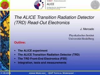
The optical readout chain for theALICE Transition Radiation Detector Presentation at IRTG Seminar Felix Rettig 29. Juni 2007
Outline • The ALICE Experiment • The Transition Radiation Detector (TRD) • Optical Readout Interface Board (ORI) • features, high-speed laser modulation • error rates, irradiation test results • Readout datapath components • Global Tracking Unit (GTU) and its sub-components • low-latency transmission for triggering • high-bandwidth buffering of raw data • multi-event data buffering • Current Status of GTU development and assembly • Outlook
ALICE Experiment • Pb-Pb collisions at up to 1150 TeV • 8000 collisions per second • Goal: Quark-Gluon- Plasma • Various detectors: TPC, TRD, ... A Large Ion Collission Experiment (ALICE)
Transition Radiation Detector • 1.2 million channels • 65664 MCMs
Transition Radiation Detector Cathode Pads • 1.2 million channels • 65664 MCMs AnodeWires Ampl. CathodeWires Drift Chamber Drift Radiator z y
deflection time bins y TRD Front-End Electronics (FEE) Local Tracking • Multi-Chip Module (MCM) • 10-bit ADC for each of the 18 channels • up to 32 time bins, 10 MHz sampling rate • ADC raw data reduction to stiff "tracklets" characterized byy-, z-position and deflection (compound 32-bit value) PASA Tracklet Processor (TRAP) 10 Filter Preprocessor Processor Network Interface Data Buffers ADC ...18x... Readout Tree Analog signals from 18 cathode pads ... 10 ADC Multi-Chip Module (MCM)
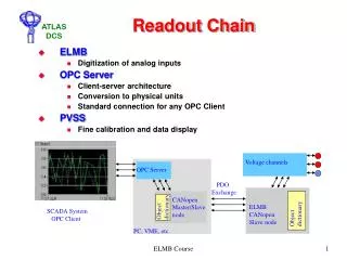
TRD FEE Readout Tree z • Readout Board (ROB): • 16 MCMs in readout tree • 4 column mergers • 1 board merger • Module: • 2x 4(3) Readout Boards • 2 Half-Chamber Mergers • 2 Optical Readout Inter-face Boards (ORI) • half chamber data concen-trated by HC Merger • optical transmission from ORI to Global Tracking Unit outside of L3 magnet y C C C C C C C C C C C C C C C C Board Merger Board Merger Board Merger Board Merger HC Merger 2 x 72 Channels Optical laser link toGTU located outsideof L3 magnet ORI-Board 2x per Module 12 or 16 Pad Rows The full TRD comprises • 65664+ MCMs on 4104 ROBs • 540 modules in 90 stacks • 1080 optical readout links
Optical Readout Interface Board Key features: • conversion 120 MHz 8-bit DDR to 125 MHz 16-bit SDR • 8B/10B encoding and serialization to 2.5 Gbit/s • high-speed modulation of laser driving signals • 850nm Laser Diode (VCSEL) with Monitoring Diode 120 MHz 125 MHz 2.5 GHz HC-MCM CPLD LVDS 8B/10BSerial. LaserDriver LaserDiode I²C bus PROM ROB
Optical Readout Interface Board Connectors toReadout Board LVDSTransceivers LaserDriver LaserDiode 8B/10B EncoderSerializer CPLD
Laser Diode • Vertical Cavity Surface EmittingLaser Diode (VCSEL) • built-in monitoring diode forpower regulation feedback Iforward C
IM Rng IMD Nom IM Rng APC Gain IMD TC1,2 IM TC1,2 Peaking IM Nom TNom IM Gain Laser Modulation - Shunt Switching Laser Driver IMD CURRENTATTENUATOR LOG ADC APC Mode AMP - S DAC + C IS Temp Servo Controller Comp Source Current TempSensor + RT ADC - IM ILD Servo Controller Temp I tc 1 / tc 2 Modulation Current Comp M + S DAC - LaserDiode MonitorDiode diff.datasignal + - ADC DAC
eye closed big parameter space: 15 setup parameters in combination with various properties of board components determinelow- and high-speed characteristics of laser driving signals hard to find a common setup to be used for all 1080 boards very fast signals to be optimized, intricate to measure Laser Modulation - Eye Diagrams 250ps LaserForwardCurrent 8mA eye closed clear eye opening
eye closed huge parameter space: 15 setup parameters in combination with various properties of board components determinelow- and high-speed characteristics of laser driving signals hard to find a common setup to be used for all 1080 boards signals to optimize are very fast, intricate to measure Laser Modulation - Eye Diagrams 250ps 125ps LaserForwardCurrent 8mA 6mA eye closed clear eye opening final setup with "peaking"
ORIs in first Supermodule at CERN • high reliability of data transmission achieved: • broad safety margin ensures sufficient opti-cal power in case of laser degeneration • laser diodes operating in lower region of forward current and optical power output First Supermoduleinstalled at CERN Bit Error Rates < 10-15 Number of Optical Links minimum powerfor BER <10-10 Optical Power [µW]
ORI Irradiation Tests • Irradiation tests carried out at OCL • 27.7MeV proton beam • All components meet safety margin of factor 4 life-time Assumptions about TRDradiation environment: DIP ~ 1.6 Gy, Dtot ~ 1.8 Gy in 10 years of operation
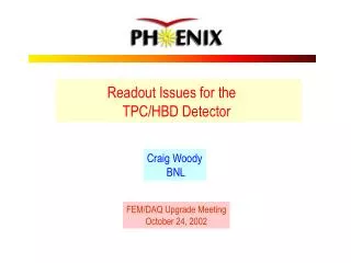
Full TRD Readout Chain • Global Tracking Unit (GTU) • Track Matching Unit (TMU) • Supermodule Unit (SMU), Trigger Generation Unit (TGU) GTU Racks TGU CentralTriggerProcessor x 8 1 5x TrackConcentr. 6 x TriggerDesign Trackletsonly Half Chamber ORI TriggerHandling &Control DCSBoardTTCrx RX 12 fibres ORI Event BufferingDesign DDLSIU DATESoftware DIU Module Tracklets&Raw Data D - RORC TMU SMU Stack 5 x GTU Supermodule Segment Mass Storage Front-End Electronicswithin L3 magnet Racks belowMuon System Storage DAQ System
Collision - PreTrigger Level-0Trigger Level-1Trigger Drift Time Fit Calculation Tracklet Building Raw Data Shipping Tracklet Shipping Global Tracking TRD Level-1 Trigger Contribution Shipping 0 1 2 3 4 5 6 7 8 Time after Collision [µs] ALICE Trigger Timing Collision Level-0Trigger Level-1Trigger Level-2 Trigger Window 1.2 6.2µs 73.8µs Accept/Reject 493.8µs Tracklets Raw Data Data Forward to DAQ Time after Collision
GTU Requirements • 1080 optical links deliver both • tracklets: low-latency required, small volume, high rate • raw data: big volume, latency subordinate, lower rate • huge bandwidth • each opical link: 1.94 Gbit/s • links into one TMU: 23.3 Gbit/s • full detector: 2.1 Tbit/s = 244 GByte/s • fast track reconstruction and decision taking for TRD'slevel-1 trigger contribution • uni-directional optical links, no flow control • buffering of incoming raw data with full bandwidth • forward buffered event data to DAQ system or discard • support for trigger interlacing, buffering of multiple events
TMU Requirements • low-latency deserialization and 8B/10B decoding ofoptical data received from front-end electronics • 12 independent 16-bit data streams at 125 MHz clocks • single 4-Mbit SRAM with 128-bit interface at 200 MHz • multi-event buffering of up to five events,appropriate data forwarding or discarding on L2 messages • error detection / handling for each separate link • aborting of incomplete events, discarding associated data • delicate balance between speed and ressource utilizationto accomodate trigger and buffer designs in one FPGA → complex FPGA design, many clock domains, highly pipelined data path design needed to allow for operation at 200MHz
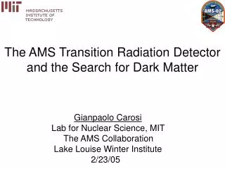
10GBASE-RBlock Sync CommaDetect 8B/10BDecode 16x52 ring buffer 2.5 GHz serial data SIPO 8B/10BDescram 10GBASE-RDecode Fabric Interface RX DataFlags ClockDividersPhaseAlign ClockControl Clocks PMA PCS Receiving of Optical Data • optical-electricalconverter modules • Virtex-4 FX100 FPGA • 16 Multi-Gigabit Transceivers • highly configurable, ~100 parameters • clock reconstruction • deserializing • comma detection,comma aligning • 8B/10B decoding • rate matching • incoming 16-bit data streams synchronized to one 125 MHz clock
Event Buffering Design Data Block, Link 0 Data Block, Link 11 Event (n, 0) Event (n+1, 0) Event (n, 11) Event (n+1, 11) 4-MbitSRAM empty ... 12x ... SRAMController DataFormatting 16/128 TMU/SMUInterface Datastream Merging data Links from one Stack ... 12x ... Supermodule Unit write read 16/128 address ReadAddressLogic &Control Scheduling Event InfoFIFO Buffer MemoryManagement Event Shaper Readout Unit status SMU Control(L0-/L1-Trigger) SMU Control(L2-Message)
tracklet data raw data 16 END commas 128 ... 12 links ... ... 12 blocks ... 16 END L1 L0 SRAM Data Stream Merging • collation of 16-bit values to 128-bit lines for each link • padding at the end of datastreams • 12 data path clock domain crossings • 12 independent 16-bit data streams at 125MHz with gaps • single SRAM with 128-bit wide interface at 200MHz 128-bit Line
Data Collation • Block-RAM primitives • 16-bit/32-bit collation • safe datapath clock domain crossing • buffering of filled 128-bit lines until scheduled forward to SRAM write • commas discarded, only valid data words are collated • write enable logic performs padding without need for extra endmarker write cycles • end of data flag stored explicitly, no 32-bit compares necessary in later stages Link Data 16 32 BRAM 0 BRAM 1 Data Valid Line Data 128 BRAM 2 writeenable BRAM 3 Last Line = End Marker writeaddress readaddress ringcounter FIFO Line Advance Line Valid 125MHzclock domain 200MHzclock domain Aligning Buffer
Buffer Organization • SRAM divided into separate parts, one for each link • blocks independently organized as ring buffers • data of multiple events dynamically • double write pointers allow discarding of incompleteevents, directly freeing occupied memory locations • overrun protection, anticipatory busy signaling Data Block, Link 0 Data Block, Link 11 Event (n, 0) Event (n+1, 0) Event (n, 11) Event (n+1, 11) 4-MbitSRAM ... 12x ... empty memory end (n+1) end (n+1) end (n) end (n) rp rp
Buffer Address Management • 2 write pointers • first word offset • current offset • normal operation: • first constant • increment current • event complete: • pointers swap meaning • discard incomplete event: • use first word pointer, copy to current pointer • only one RAM block needed for all pointers,no 12:1 multiplexers Data Block, Link 0 Event n-2 Event n-1 Event n (incomplete) ... 12x ... A B ReadPointer Write pointers base address SRAMwrite address + 18 R offset Write Pointer A0 Write Pointer A1 Bank A 1 + eventend pointer Write Pointer B0 Write Pointer B1 0 0 Bank B Block RAM writeaddress readaddress
Tests and Integration Progress • GTU segment running in Münster for super-module assembly and testing • all segments being assembled and tested currently • transfer to CERN and installation scheduled for end of july • some CTP signal handling and DDL/DAQ issues open • trigger design not yet integrated
Prospective Work • Finish development of GTU • a lot of open detail issues • multi-event buffering under full CTP control • Installation at CERN • Beam and performance tests, refinements • Monitoring system, GTU event display • Physics applications of GTU • various trigger schemes based oncomprehensive track and pt information,e.g. Jet Triggers
Thank You for Your Attention Questions?