Download
1 / 46
460 likes | 821 Views
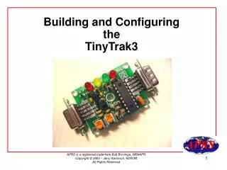
Building and Configuring the TinyTrak3. What is a TinyTrak3?

E N D
What is a TinyTrak3? TinyTrak3 is a GPS position encoder which, when connected to a GPS and a radio, will transmit its location at an adjustable rate. TinyTrak3 is a construction project providing an inexpensive way to build a mobile tracker without the need for a full TNC. It is configured by connecting to a computer's serial port, and running a simple configuration tool which allows setting of all user options. After ordering a kit or a chip, be sure to download the configuration software and documentation. Download TINYTRAK3.ZIP
What is TinyTrak3 NOT? TinyTrak3 is not a TNC (Terminal Node Controller). TinyTrak3 can only transmit data beacons it receives from a GPS receiver (NMEA 0183). You can not receive data or messages or transmit a 2 way packet QSO with a TinyTrak3. The connection to the radio’s audio output deliver audio energy to the PIC controller to prevent the TinyTrak3 from transmitting while another packet station is transmitting. It is not decoding the packets. It is just detecting audio energy at the speaker terminals.
Where to get a TinyTrak3. Orders can be placed by sending a check or money order to: Byon Garrabrant 8378 Granite Mountain Lane Las Vegas, NV 89129 Web Site: http://www.byonics.com/tinytrak/index.html TinyTrak3 Kit - $32 TinyTrak3 Built and Tested - $62 TinyTrak3 Case - $8 TinyTrak3 Chip - $18 TinyTrak3 Female To Female Gender Changer / Null Modem Kit - $4 First Class Postage - $3 Upgrade Shipping via Priority Mail - $3 Byon accepts PayPal orders via his web site.
Do this First Download and print out the TinyTrak3 Owner’s Manual from www.byonics.com/tinytrak/tinytrak3.zip. In this WINZIP file is the Owner’s Manual in PDF format and the necessary configuration software called, “tinytrak3config.exe”. Also are the files for using the TinyTrak3 with a Palm handheld computer.
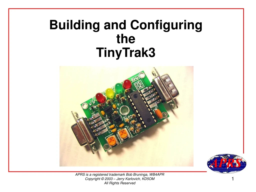
Familiarize yourself with the Printed Circuit Board. Notice the Correct position of U1, U2, Q1, the 4 LEDs and the 3 Diodes.
Consider where and how you are going to mount your TinyTrak3 before soldering any parts. This may determine weather or not you will need to put it in a case or attach the DB9 connector to the radio end.
Bend the leads slightly to keep the parts from falling out while soldering.
Cut the excess lead with a flush cutter or diagonal wire cutter.
Make sure the DIP socket is flush before soldering all 18 points. Begin by soldering only two diagonal opposite points first. Check to see that it is flush then solder the rest.
Notice that the resistor bodies are inline with the circles on the PCB. The other bent lead goes into the corresponding hole.
Another view of the resistors mounted on the PCB. The 10MHz resonator can go in either direction. It has no polarity.
To apply power to pin 4 on the GPS DB-9 connector if needed.
To apply power to pin 4 on the GPS DB-9 connector if needed.
Jumper 4 - Controls the LEDs (N.C.). Jumper 5 - Primary or Secondary configuration. Jumper 6 - Remote power switch.
Finish soldering all of the remaining components to the PCB. Be extremely cautious while handling the PIC. Use a grounded wrist strap or touch a metal object before handling it. Take notice of the position of the notched end of the PIC.
The configuration cable, alias “Gender Changer/Null Modem” is easily made from 2 female DB-9 connectors and three pieces of wire. Cross-over pins 2 & 3 and straight through on pin 5.
Monday, September 1, 2003 at about 3:15pm, I found John Beadles N5OOM, returning home on Interstate 20 near Birmingham, AL.
Inside a modified DeLorme Tripmate GPS receiver. Just add a radio.
I bent the LED’s leads in a 90 degree fashion. Then drilled holes in alignment so the LEDs can protrude through the holes.
This is KD5OM-2 mobile TinyTrak3. The TT3 is in the upper left hand corner. The transceiver is a Kenwood TH21at ($20.00 find at a ham fest). What’s in the Altoids tin?
A ten watt 2 meter amplifier. The Altoids tin gave excellent RF shielding. TinyTrak3s are sensitive to high RF environments.
Here is a close-up of the TinyTrak3 inside my mobile tracker. Notice the jumper on J5.
What other options are there available for the GPS receiver? Here is a Garmin etrex receiver that cost around $125.00 in many stores. A data cable is also available for it that will connect directly to the TinyTrak3.
You can receive a lot of help from the TinyTrak discussion group on Yahoo.
Wiring the TinyTrak3 to your 2 meter radio is the same cable as the KANTRONICS KPC-3 uses.
You can find wiring harness information at:www.packetradio.com/tnc2rad.htm#KANTRONICS