Download
1 / 16
170 likes | 221 Views
Series Circuit Applied Physics and Chemistry Circuit Lecture 3. Symbols Used. Series. Circuit in which current passes through all resistors Only one path for current Each resistor uses up some of the potential V source = V a + V b +. Resistance.

E N D
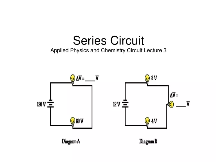
Series CircuitApplied Physics and Chemistry Circuit Lecture 3
Series • Circuit in which current passes through all resistors • Only one path for current • Each resistor uses up some of the potential • Vsource = Va + Vb + ....
Resistance • Equivalent resistance (effective resistance) for devices in a series circuit is sum of individual resistances • R = R1 + R2 + R3 + …
Current • Current in a series circuit is the source voltage divided by the equivalent resistance • Current is the same everywhere in the circuit • Icircuit = Vsource/Req
Example • Two resistors, 47Ω and 82Ω, are connected in series across a 45V battery. What is the current in the circuit? What is the voltage drop at each resistor? • Known: R1=47Ω R2=82Ω V=45V • Req = R1 + R2 • Req = 47Ω + 82Ω = 129Ω
Example Continued • Current in the resistor: I = V/R • I = 45V/129Ω = 0.349 A • Voltage at resistor 1: V = IR • V=(0.349 A)(47Ω) = 16.4 V • Voltage at resistor 2: V = IR • V = (0.349 A)(82Ω) = 28.6 V
Example Continued • Will current increase, decrease or stay the same if the 47Ω resistor is replaced by a 37Ω resistor? • New Req = 37Ω + 82Ω = 119 Ω • I = V/R = 45V/119Ω = 0.378 A • Current increases
Example Continued • What is the new voltage drop at resistor 2? • V = IR • V = (0.378 A)(82Ω) = 31V
Series Circuit Uses Series circuit can be used as a voltage divider If a certain resistance needs a specific voltage, series circuit can be used to provide that Example p 406 A 9.0 V battery and two resistors R1= 400 Ω and R2 = 500 Ω are connected as a voltage divider. What is the voltage across R2?
Parallel Circuit • Multiple pathways for current • Total current is the sum of the currents at each resistor (Current is NOT the same everywhere) • Potential difference is the same everywhere in the circuit
Parallel Circuit • Equivalent resistance is reciprocal • 1/Req = 1/R1 + 1/R2 + 1/R3 … • Placing resistors in parallel always decreases the equivalent resistance of the circuit
Example • Three resistors, 60Ω, 30Ω, and 20Ω, are connected in parallel across a 90V battery. Find the current through each branch of the circuit. Find the equivalent resistance. Find the current through the battery. • Known: R1=60Ω R2=30Ω R3=20Ω V=90V
Example Continued • Current at R1: I=V/R I=90V/60Ω=1.5A • Current at R2: I=V/R I=90V/30Ω=3 A • Current at R3: I=V/R I=90V/20Ω=4.5 A • Equivalent Resistance: 1/Req=1/60Ω + 1/30Ω + 1/20Ω = 6/60Ω • Req = 10Ω • Total Current: I=V/R I=90V/10Ω I=9 A


![[Series Circuit]](https://cdn1.slideserve.com/2747272/series-circuit-dt.jpg)