Download
1 / 1

E N D
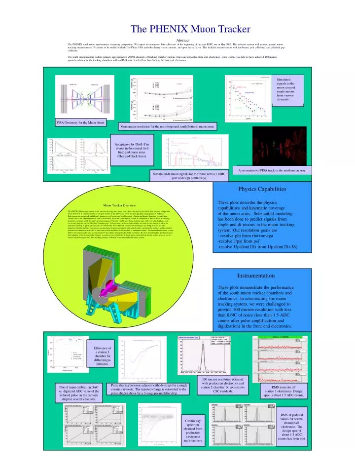
The PHENIX Muon Tracker Abstract The PHENIX south muon spectrometer is nearing completion. We expect to commence data collection at the beginning of the next RHIC run in May 2001. This detector system will provide general muon tracking measurements. Processes to be studied include Drell/Yan, J/Psi and other heavy vector mesons, and open heavy flavor. This includes measurements with ion beams, p-A collisions, and polarized p-p collisions. The south muon tracking system contains approximately 20,000 channels of tracking chamber cathode strips and associated front-end electronics. Using cosmic ray data we have achieved 100 micron spatial resolution in the tracking chambers with an RMS noise level of less than 2mV in the front-end electronics. Simulated signals in the muon arms of single muons from various channels. PISA Geometry for the Muon Arms. Momentum resolution for the north(top) and south(bottom) muon arms. Acceptance for Drell-Yan events in the central (red line) and muon arms (blue and black lines). A reconstructed PISA track in the north muon arm. Muon Tracker Overview The PHENIX Muon Arms detect vector mesons decaying into muon pairs, allow the study of the Drell-Yan process, and provide muon detection in semileptonicdecay of open charm, in the relativistic heavy ion and spin physics programs of PHENIX. Each muon arm must track and identify muons, as well as provide good rejection of pions and kaons; therefore, both a Muon Tracker (µTr) and a Muon Identifier (µID) are needed. Each arm of the Muon Tracker is comprised of three stations of tracking chambers, mounted inside the end-cap muon magnets. Stations 1 and 2 have three chamber gaps with two cathode planes read out in each gap and station 3 has two chamber gaps. Various stereo and non-stereo angles are used at each station to allow for maximal rejection of ghost intersections of cathode hits. Two different construction techniques are being used for the µTr chambers: the first and last stations are constructed as honeycomb panels with cathode strips on the inside surfaces and the central stations are constructed as stacks of wires and etched metallized foils attached to aluminum frames. The muon identification system follows the muon tracker and is comprised of 6 steel plates interspersed with Iarocci tubes. The first absorber plate also functions as the backplate of the muon tracker magnet. A cutaway view of the North muon arm is shown below. In this picture you can see the conical shaped magnet with three tracking stations, followed by the muon identification system. Simulated di-muon signals for the muon arms (1 RHIC year at design luminosity). Physics Capabilities These plots describe the physics capabilitites and kinematic coverage of the muon arms. Substantial modeling has been done to predict signals from single and di-muons in the muon tracking system. Out resolution goals are - resolve phi from rho+omega -resolve J/psi from psi’ -resolve Upsilon(1S) from Upsilon(2S+3S) Instrumentation These plots demonstrate the performance of the south muon tracker chambers and electronics. In constructing the muon tracking system, we were challenged to provide 100 micron resolution with less than 0.6fC of noise (less than 1.5 ADC counts after pulse amplification and digitization) in the front end electronics. Efficiency of a station 2 chamber for different gas mixtures. 100 micron resolution obtained with production electronics and station 2 chamber. X axis shows CSC residuals. Plot of input calibration DAC vs. digitized ADC value of the induced pulse on the cathode strip for several channels. Pulse sharing between adjacent cathode strips for a single cosmic ray event. The injected charge is converted to the pulse shapes above by a 3-stage preamplifier chip. RMS noise for all station 1 electronics. Design spec is about 1.5 ADC counts. RMS of pedestal values for several channels of electronics. The design spec of about 1.5 ADC counts has been met. Cosmic ray spectrum obtained from production electronics and chambers.