Download
1 / 27
310 likes | 461 Views
Microprocessor. Dr. Rabie A. Ramadan Al-Azhar University Lecture 2. Input / Output. Input Devices Switches , Keyboard , …. Output Devices: Seven Segments (LEDs) , printer , Monitor ,..

E N D
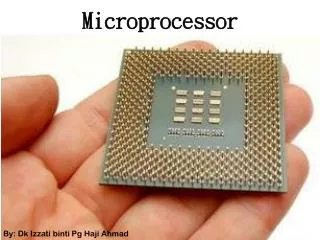
Microprocessor Dr. Rabie A. Ramadan Al-Azhar University Lecture 2
Input / Output • Input Devices • Switches , Keyboard , …. • Output Devices: • Seven Segments (LEDs) , printer , Monitor ,.. • The processor reads the instructions from the memory , data from the input devices, processes them, produces the output
Microprocessor as CPU -The CPU includes ALU, control Units , and Various Registers -Known as Microprocessor
The Von Neumann Model It uses von Neumann execution cycle (also called the fetch-decode-execute cycle)
The Von Neumann Model (Cont.) A cycle could be as follows: The control unit fetches the next program instruction from the memory, using the program counter to determine where the instruction is located. The instruction is decoded into a language the ALU can understand. Any data operands required to execute the instruction are fetched from memory and placed into registers within the CPU. The ALU executes the instruction and places the results in registers or memory.
Instruction Processing Von Neumann execution cycle Fetch instruction from memory Decode instruction Evaluate address Fetch operands from memory Execute operation Store result
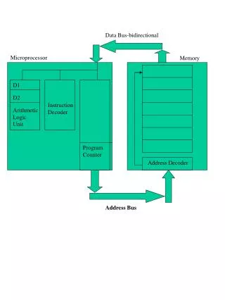
The Modified Von Neumann Model The data bus: Moves data from main memory to the CPU registers (and vice versa). The address bus: Holds the address of the data that the data bus is currently accessing. The control bus: Carries the necessary control signals that specify how the information transfer is to take place.
Advances in Semiconductor Technology • IC- Integrated Circuits few transistors and diodes on one chip • SSI –small scale Integration few gates on one chip • MSI- Medium scale Integration- 100 gates on a chip • LSI – Large Scale Integration – 1000 gates on a chip • VLSI – Very large scale Integration • SLSI – Super Large Scale Integration • Borders between VLSI and SLSIare not strict.
Microprocessor Programming • Machine language • Instruction written in binary format • Assembly language • Text based format Add A , B • High level Language Source Code Compiler / Interpreter Object Code
Z80 Instructions and Alphanumeric Codes • 8-bit word length • 158 instructions • ASCII – American Standard Code for Information Interchange. • Each character has its equivalent binary format in a 7-bit code • EBCDIC – Extended Binary Coded Decimal Interchange Code – 8-bit code
Reading Assignment • Please read Chapter 1 in the textbook
Microprocessor-Based System Microprocessor Memory I/O
Microprocessor Unit • Programmable logic unit with a designed set of instructions • What it does: • Fetches the instructions from the memory, one by one • Reads the input data from the input units • Performs the data manipulation specified by the instruction • Writes the data to the output devices
Microprocessor Unit • MPU frequently communicates with the memory, I/O devices • Fetch, Decode, and Execute operations • Can it be interrupted ? • Program initiated operation – interrupt done by a program. • Peripheral initiated operation – interrupt done by external devices • E.g. important data on the input during writing to the printer
What does it needs to do so.. • Group of logic circuits • Set of signal to transfer information • Control signals for timing • Clock circuits
Program-initiated operations and Buses • Microprocessor and Memory Operations • Memory Read • Reads instructions or data from the memory • Memory Write • Writes instructions and data into memory • I/O Read • Accepts data from input devices • I/O Write • Writes data to output devices
Program-initiated operations and Buses • From where to read or to write? • We need an address! Right? • How the input/output will know about the operation? • We need a control signal to tell them • MPU Operations Steps: • Identify the address • Send synchronization SIGNAL– control signal • Transfer the binary data • So, how many buses do we need?
Buses • Address Bus • Identify the memory locations • Data Bus • Holds the data during transfer operation • Control Lines • For timing signal
Buses • Address Bus Size - bits • Depends on the number of memory locations that can be accessed • Z80 has 16 address lines to address 216 locations • Data Bus Size - bits • Depends on the data to be transferred • Z80 has 8 bits data bus • What is the maximum memory size Z80 can use?
Externally Initiated operation • Interruptions categories : • Reset – e.g. timer to reset everything in the MPU • Interrupt – stop temporarily and do something , then come back. • Wait: the memory can not handle the MPU request , wait signal must be generated. • BusRequest: sometimes the processor is too slow to hand a request that can be handled faster by another device. • E.g transfer large amount of data through the DMA could be faster than using the MPU
Memory • Memory Cell
Memory Continue • 4-bit Register
4 X 8 bit register Input WR Input Buffer Memory Unit Register 3 A1 Register 2 2-to-4 Decoder A0 Register 2 Register 0 RD Output Buffer Output
How the MPU Writes into the Memory? • MPU places the 16 bit address on the address bus • Memory interfacing circuits will decode address to specify the target register • MPU Places a byte on the data bus • MPU sends a control signal (Memory Write) to the memory to write
How the MPU reads from the Memory? • MPU places the 16 bit address on the address bus • Memory interfacing circuits will decode address to specify the target register • MPU sends a control signal (Memory Read) to the memory to enable the output buffer • The memory puts the data on the data bus and the processor will read it
Reading Assignments Plead read chapter 2 See you on Tuesday