Download
1 / 53
530 likes | 755 Views
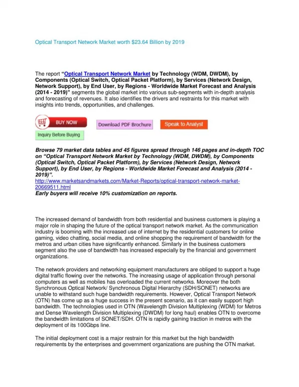
State and future of optical transport networks. RoEduNet conference Cluj, 28 th August 2008 Andreas Hegers Director Solutions Architecture and Strategy Metro Ethernet Networks. Agenda. Market trends Main Services and Bandwidth drivers Technology trends Key network requirements

E N D
State and future of optical transport networks RoEduNet conference Cluj, 28th August 2008 Andreas Hegers Director Solutions Architecture and Strategy Metro Ethernet Networks
Agenda • Market trends • Main Services and Bandwidth drivers • Technology trends • Key network requirements • Ways to build a future-proof transmission network • DWDM transmission • 10G - Still the baseline • 40G - The next big thing • 100G - On the horizon • Networking flexibility • ROADMs - Photonic flexibility • OTN - The successor of SDH (?) • L2 - Embedded data capabilities • Control plane - Gluing it all together • Network example RoEduNet • Outlook and summary
Agenda • Market trends • Main Services and Bandwidth drivers • Technology trends • Key network requirements • Ways to build a future-proof transmission network • DWDM transmission • 10G - Still the baseline • 40G - The next big thing • 100G - On the horizon • Networking flexibility • ROADMs - Photonic flexibility • OTN - The successor of SDH (?) • L2 - Embedded data capabilities • Control plane - Gluing it all together • Network example RoEduNet • Outlook and summary
10/100M 1G 10G 3.0 Source: Infonetics 2H 2007 10/100M 44%CAGR (07-10) 1G 36% CAGR (07-10) 10G 415% CAGR (07-10) 2.5 2.0 1.5 EADs (Millions) 1.0 0.5 0.0 2007 2008 2009 2010 The Need for Speed • YouTube today uses as much bandwidth as the entire Internet in 2000: • 200 Tbytes of traffic daily More than 70% of U.S. Internet users, streamedor downloaded Web videoin 2007. By 2010, 27% of Business access will require 100M - 10G Ethernet • Storage bandwidth growth: • 6,000,000 Terabytes 2008 -> > 16,000,000 Terabytes 2010 Gartner Group, Oct 2006 We are in the middle of massive growth of networks where bandwidth requirements are exploding. Source: Infonetics & Nortel Analysis
2004 2005 2000 2001 2002 2003 2006 2007 2008 2009 Source: Infonetics, 2Q06 & Nortel internal 100G study Impact on Transport 100 Gbps • Sum of capacities from various user groups builds need for 40Gb/s and eventually 100Gb/s links • Video and voice services drive more stringent QoS expectations • Optical (data center) services require multi-Gb/s over full time or on-demand connections Terrestrial Gbps Routes 4.4% 5.4% 10.5% 40 Gbps 21.4% Gbps Routes in Millions (represents new ports shipped) 10 Gbps 2.5 Gbps
Residential Services Access Wireless Backhaul Key Enabling Technologies – Optical Access Metro L H Core Transport & Service Management Business Services Access Ethernet PDH / SDH IP Optical Modem: Fully Tuneable10 40 100 Gbs Adaptive Distortion Mitigation (CD, PMD/PDL, Non-linearities) Agile Packet Optical WSS based ROADM for l network agility, multi-way branching Photonic domain control intelligence for fully automated line control and simplified end to end provisioning GbE Storage Leased Lines Converged L0/L1/L2 in single platform for fully flexible capacity allocation BB Business Services Access
Residential Services Access Wireless Backhaul Ethernet with the Efficiencies of Packet and the Robustness of SDH Key Enabling Technologies – Ethernet Access Metro L H Core Transport & Service Management Business Services Access IP / MPLS Ethernet PDH / SDH IP PBB-TE (PBB-TE) Deterministic Ethernet Circuits GMPLS provisioning efficiencies Carrier Ethernet 802.1ag and Y1731 carrier grade operations and instrumentation Ethernet Agile Optical PBB – secure, scalable clear demarcation between customer and provider addressing GbE Storage Leased Lines BB Business Services Access
Agenda • Market trends • Main Services and Bandwidth drivers • Technology trends • Key network requirements • Ways to build a future-proof transmission network • DWDM transmission • 10G - Still the baseline • 40G - The next big thing • 100G - On the horizon • Networking flexibility • ROADMs - Photonic flexibility • OTN - The successor of SDH (?) • L2 - Embedded data capabilities • Control plane - Gluing it all together • Network example RoEduNet • Outlook and summary
Network Simplification Through Innovation C-Band OEO DSCM DSCM OEO DSCM … … DSCM DSCM OEO OEO Terminal Node L-Band OEO … OEO … DSCM DSCM DSCM DSCM DSCM OEO OEO AMP Node OEO OADM Node Electrical Signal Processing Advanced FEC Advanced line and modem Remove/Minimize DSCMs & Amps, Increase PMD Tolerance, Eliminate complex engineering rules (esp. OADM) Improved coding-gain Simple deployment & reconfiguration, reduced inventory & truck rolls eROADM Node Terminal Node AMP Node OEO OEO OEO … … OEO OEO
Advanced E/O Modem Introduction • 10G eDCO • Electrical Tx based dispersioncompensation • Better than+/- 50,000ps/nm • Real-timeFully automatic • Wraptor FEC • 9.4dB of coding gain • 3dB > RS-8 • Raman avoidance 2003 2005 2008 Future Embedding Transmission Complexity into Electronics 10
Rx Rx Tx Tx 1 span Pre-Distorted, Eye Diagram Focused Eye Diagram(Zero Net Dispersion) Optical Pulse Transmission with Electronic Dispersion Compensation (eDCO) on a 10 Gb/s link Conventional Optical Link with DCMs DCF DCF DCF DCF DCF = Dispersion Compensating Fiber, packaged as a DCM Nortel’s Next Generation Optical Link with CPL and eDCO
eDCO Dispersion Scan 20 spans - 1.600 km Dispersion [ps/nm] 22,000 22,250 22,500 22,750 23,000 23,250 23,500 23,750 24,000 24,500 24,750 25,000 25,250 25,500 25,750 26,000 26,250 26,500 26,750 27,000 24,250 But what about 40G…?
Fiber parameters - Things to know • The key fiber parameters to pay attention to are • Attenuation: • Chromatic Dispersion (CD): • Polarisation Mode Dispersion (PMD): For 40G, the limiting factor is mostly PMD • Many carriers don‘t know the PMD values of their fiber, thus we have to stress the importance • The older a fiber, the higher usually it‘s PMD. One bad part will spoil the complete link • At 100G, the situation is much worse for all 3, so a future proof solution is key
40 Gbps TDM – Challenges vs. 10 Gbps • 4 times the baud rate of 10G TDM • Bit interval reduced from 100ps to 25ps • Circuit implementation significantly more challenging also need more complex materials • 4 times less light entering the receiver • 6dB drop in noise margin, may need RAMAN amplifiers • Increase optical spectrum occupied by a factor of 4 (to ~ 6 RZ) • Increased system impact of optical filters (OADM/ROADM) • 16 times less tolerant to chromatic dispersion • More stringent dispersion map • Increased installation difficulties, needs to be engineered day one • May need active CD compensators • 4 times less tolerance to PMD • May need PMD compensators • May need to select/match fiber based upon vintage, installation, etc… 40G/ transmission has Significant Optical Challenges
Advanced E/O Modem Introduction • eDC40 • 2-Pol QPSK 40G • 10Gbaud operation • +/- 50,000 ps of CD compensation • Electrical PMD mitigation • 50GHz OADM compatible • 10G eDCO • Electrical Tx based dispersioncompensation • Better than+/- 50,000ps/nm • Real-timeFully automatic • Wraptor FEC • 9.4dB of coding gain • 3dB > RS-8 • Raman avoidance 2003 2005 2008 Future Embedding Transmission Complexity into Electronics 15
40 Gbit/s on a single wavelength at 10 GBaud Using Quadrature Phase Shift Keying (QPSK) 2 bits/symbol: X 2 2 QPSK signals, one per polarization 2 orthogonal polarizations: X 2 World’sfirst fully integrated 40G coherent digital receiver Propagates like a 10 Gbps signal For non-linear impairments, dispersion tolerance, PMD tolerance, etc… Uses 10G components: cost optimized, mature technologies with numerous vendors Fully leverages existing 10G Line Infrastructure Same Reach – No RAMAN or reduction to overcome increase in noise Same tolerance of cascaded ROADMs No Dispersion Compensation required Better PMD Performance than 10G systems All fiber that could be used for 10G can nowbe used for 40G 40 Gbps Dual Polarization QPSK Dual Polarization Vertical Polarization Horizontal Polarization Dual Polarization QPSKX - polarization Q (0,1) (0,0) I (1,1) (1,0) QPSK Y- polarization (0,0) (0,1) Q I (1,0) (1,1) Rx Data Before DSP Rx Data After DSP
40 Gbps Dual Polarization QPSK 40GDual PolarizationQPSK 50 GHz 10GConventionalTDM 40GConventionalTDM Frequency 40G TDM Severely Impacted by Cascaded ROADMs System Severely Limited at 50GHz-Spacing Carries Less Traffic
40G Modulation SchemesPerformance Comparison But what about 100G…? 2-POL QPSK looks like the right solution
Customers want bigger pipes Why 100G?
100G - Things to know • 100G is seen as the next big step for all vendors • First deployments are expected around 2010 timeframe • Given the lifetime of a transmission network, whatever is rolled out today should be 100G ready • As the need for higher network capacities is there, a sit-and-wait strategy is no option • Given the complexity of 100G transmission, only vendors with solid 40G knowledge & ASIC implementation have a realistic chance to get there in time
Advanced E/O Modem Introduction • eDC100 • 100G/l • Reach > 1000Km • Electrical CD and PMD compensation • 50GHz OADM compatible • eDC40 • 2-Pol QPSK 40G • 10Gbaud operation • +/- 50,000 ps of CD compensation • Electrical PMD mitigation • 50GHz OADM compatible • 10G eDCO • Electrical Tx based dispersioncompensation • Better than+/- 50,000ps/nm • Real-timeFully automatic • Wraptor FEC • 9.4dB of coding gain • 3dB > RS-8 • Raman avoidance 2003 2005 2008 Future Embedding Transmission Complexity into Electronics 21
100G Standards UpdateITU Study Group 15 Q6 Meeting – Oct 2007 • ITU determining next rate of OTN (OTU-4) to accommodate 100GbE • OTU-4 rates considered: • 3 X 40G -> 130 Gbit/s • 100 GbE -> 112 Gbit/s (most popular) • Decision on rate to be made end 2008 • Advanced modulation schemes consideredto support the new rates: • Dual Polarization (Dual Pol) or Polarization Multiplexed QPSK, Duobinary, DQPSK, RZ-DQPSK. • Dual Polarization QPSK • Only format capable of 50GHz spacing • Only format with 10G-equivalent PMD tolerance • Only format that could transport both OTU-4 rate proposals Expect Other Vendors to Move to Dual Polarization QPSKas Industry Moving in this Direction for 100G
Only format capable of 50GHz spacing Only format with 10G-equivalent PMD tolerance Only format that could transport both OTU4 rate proposals 100Gb/s Study Group Format Comparison Nortel Confidential
Agenda • Market trends • Main Services and Bandwidth drivers • Technology trends • Key network requirements • Ways to build a future-proof transmission network • DWDM transmission • 10G - Still the baseline • 40G - The next big thing • 100G - On the horizon • Networking flexibility • ROADMs - Photonic flexibility • OTN - The successor of SDH (?) • L2 - Embedded data capabilities • Control plane - Gluing it all together • Network example RoEduNet • Outlook and summary
The future proof transport network Ingredients to Achieve All-Optical Agility ROADMs and OTN Seamless 10/40/100G Electronic Dispersion Compensation
Traditional networks require manual patching as OADM and pass-through requirements change over time Line system optimization must be rebalanced with OADM reconfigurations Reconfigurable Optical ADM increases automation and reduces OEO costs Remote re-configurability Automatic reconfiguration for nodal wavelength pass-through events – no manual patching required Optical branching Router / DXC bypass Automated System optimization & power balancing All VOAs are electronic All power control done remotely No manual equalization ROADM Applications and Drivers ROADM ROADM ROADM Rebalance and optimize as wavelength routing changes Reconfigure with changing traffic requirements ROADM ROADM ROADM
WSS ROADM Architectures Optical bypass traffic • 2-Degree ROADM • Terminates wavelength services or passes them transparently through in the optical domain (no transponders / regenerators) • Connected to two fiber pairs (degree two) • Multi-degree ROADM • Connected to at least three fiber pairs • Can lead to cross connections restrictions or scalability issues • Directionally Independent OADM • Guarantees non-blocking wavelength switching between fiber pairs • Allows any wavelength to be re-routed to any path on the network without manual intervention Add/drop and regen traffic Optical bypass traffic Add/drop and regen traffic Optical bypass traffic Dir2 DirN Dir1 Directionally Independent Add/Drop
Starplane http://www.starplane.org/
DAS-3 Network Overview Amsterdam Free University (VU) University of Amsterdam (UvA) VLE (Virtual Laboratory for E-science) University of Amsterdam (UvA) Media lab City ring? Cluster with blade PCs SURFnet CPL 8*10G bandwidth Between each Node pair on CPL ring Leiden University (UL) Delft University (TUD)
Chosen Implementation - One band in SURFnet6 Ring 1 (Green ring) allocated to DAS-3 - Dynamic switching using WSS and OME But what about OTN…?
The idea behind OTN • The G.709 frame structure was defined to provide OAM for monitoring end-to-end services and protection capabilities for optical services, i.e. wavelength services • It supports the use of standard FEC and enhanced FEC when needed and inherently provides 3R functionality • The frame structure was defined for 3 wavelength bit rate; 2.5 Gbit/s, 10 Gbit/s and 40 Gbit/s (to match with the SDH clients) • Support of sub-wavelength services was not considered, as they could be provided by client layer networks SDH. IP L3: IP/MPLS ATM/FR MPLS L2: Ethernet SDH/PDH WDM L1: OTN
Reasons for the OTN Evolution • 10GbE • Bit transparent transport of 10 GE (10GBase-R) requires an over-clocked ODU2. A number of proprietary implementations provide the required transparency. • Transparent transport 4 x 10 GE LAN over 40 Gbit/s • Requires a mapping into an over-clocked ODU2 and multiplexing of them into a new over-clocked ODU3. One further new function is needed. • The clock tolerance of ± 100 ppm requires a new multiplexing method of ODU2e • The use of the standard multiplexing method requires a new bit-asynchronous mapping of 10 GE • 40 GE could be mapped into the standard ODU3 when transcoding is used. • 100 GE over a single wavelength requires a new ODU4. • SDH supports transparent transport of 1GE, but SDH will be switched off. Direct transport over the OTN requires a new sub-ODU1/ODU0. • The OTN must be timing transparent for Ethernet CBR signals in order to support Synchronous Ethernet
OTN Extensions Agreements OTUk/ Higher Order ODU Lower Order ODU CBR Clients XXX classical OTU or ODU new agreed OTU or ODU XXX NEW OTU4 100 GE H-ODU4 1x new OTU, ODUnot yet agreed 100 Gbit/s XXX 2x 40 GE 1x standardized mappingor multiplexing 40 Gbit/s ODU3 STM-256 1x 1x ODU3 OTU3 new agreed mappingor multiplexing 4x 10x 1x 10 GE ODU2x 16x 1x ODU2 10 Gbit/s STM-64 1x OTU2 ODU2 4x 1x 1x ODU1 STM-16 OTU1 2.5 Gbit/s NEW 1x 1 GE ODU0
Outlook on OTN Extensions OTUk/ Higher Order ODU Lower Order ODU CBR Clients XXX classical OTU or ODU L-ODU4 1x new agreed OTU or ODU XXX OTU4y 100 GE H-ODU4 1x new OTU, ODUnot yet agreed 100 Gbit/s XXX 2x OTU3y ODU3y 40 GE 1x standardized mappingor multiplexing 40 Gbit/s ODU3 STM-256 1x 1x OTU3 4x ODU3 new agreed mappingor multiplexing 10x 16x mapping or multiplexingnot yet agreed 1x OTU2y 10 GE ODU2y ODU2x 1x ODU2 10 Gbit/s STM-64 1x OTU2 ODU2 4x 1x 1x ODU1 STM-16 OTU1 2.5 Gbit/s 8x 1x 1 GE ODU0
Ingredients to Achieve All-Optical Agility The future proof transport network L2 Awareness ROADMs and OTN Seamless 10/40/100G Electronic Dispersion Compensation
Packet Optical Solutions are deployed in private builds, shared infrastructure and managed services solutions. MSPP Network Applications Multimedia Collaboration • Broadband Multiplexing • Ethernet Services Delivery MSPP Voice (VoIP) • SAN Extension • Broadband Multiplexing • Ethernet Services Delivery 40G Storage/ILM Broadband • Infrastructure (ROADM vs OMX) • Ethernet Services Delivery Photonic Operations Interconnect
Network Applications - SAN Extension Transactions performed locally Data stored / backed up Remotely OME 6500 OME 6500 OME 6500 Metro Network Transaction Transaction Transaction Transaction Database /Storage Array Database /Storage Array OM5000 OM5000 Addresses SAN Extension with requirements of intermediate multiplexing of services
OME OME Fiber MPLS Core DWDM/ SONET/ Ethernet Copper/ fiber Fiber Metro/WAN Copper OME 61x0 OC3/12/48 OME 6500 N x 2.5G OM 3500 Network Applications - Ethernet Services Ethernet VPN solutions on any of the converged layers
Ingredients to Achieve All-Optical Agility The future proof transport network Control Plane L2 Awareness ROADMs and OTN Seamless 10/40/100G Electronic Dispersion Compensation
Optical Network Automation Objectives Optical Control Plane • Network Topology Discovery and Awareness • Automated Service Activation • Can be “Client” or “Operator” driven • OEO & OOO technology provides economical flexibility • OEO for Service adaptation, network adaptation and monitoring • OOO for photonic flexibility / re-configurability • Leads to Network protection / restoration • Potential for IP / Optical inter-working via GMPLS signaling Optical Layer
Optical Control Plane Optical Layer Considerations when Control is Enabled • Control Plane in an Optical Network enables: • Automated service activation in optical layer • Network awareness resource status and utilization • Rapid identification / correlation of fault / resource / service • Optical protection and restoration • Ability to add a new wavelength automatically without impacting existing network Understanding the viability of the end-to-end wavelength path is critical
Mesh Restoration Failure notification I1 S1 I2 D1 • Automatic Restoration recovers traffic following a path failure • For traffic not protected by the Transport Plane (e.g. 1+1) • For backup restoration (e.g. 1+1 secondary) • Dynamic restoration scheme for best survivability and efficiency • Control plane learns location of failure in the signaling notification, computes next best route based on feedback information and re-routes each connection • No pre-computed/pre-assigned restoration path/bandwidth for higher bandwidth efficiency. Mesh Restoration will recover from multiple failures as long as b/w is available for restoration • Restoration performance is fundamentally unpredictable and non-deterministic, therefore restoration times are typically slower i.e. in the range of secs • Example: For 1+1 Path Protection CoS, Automatic Restoration may be optionally used to restore 1+1 path protection after initial failure • When a working connection fails, traffic is protection switched to protecting connection within 50ms by Transport Plane. • CP then re-creates (restores) the failed working connection to return the CoS back to the 1+1 Path Protected state. P1 P2
Ingredients to Achieve All-Optical Agility The future proof transport network Control Plane L2 Awareness ROADMs and OTN Seamless 10/40/100G Electronic Dispersion Compensation
Agenda • Market trends • Main Services and Bandwidth drivers • Technology trends • Key network requirements • Ways to build a future-proof transmission network • DWDM transmission • 10G - Still the baseline • 40G - The next big thing • 100G - On the horizon • Networking flexibility • ROADMs - Photonic flexibility • OTN - The successor of SDH (?) • L2 - Embedded data capabilities • Control plane - Gluing it all together • Network example RoEduNet • Outlook and summary
RoEduNet Next Generation Network • 4.238,8 km fiber • 57 locations • 22 OME 6500 • 18 ROADM sites • “…to offer the participants - universities, high schools, cultural, scientific and research nonprofit institutions - the means to communicate with each other…”
PASCANI PASCANI PASCANI IASI CAREI SATU MARE BAIA MARE ILVA MICA VATRA DORNEI SUCEAVA IASI IASI CAREI CAREI SATU MARE SATU MARE BAIA MARE BAIA MARE ILVA NUCA ILVA MICA VATRA DORNEI VATRA DORNEI SUCEAVA SUCEAVA NOC NOC NOC MARGHITA MARGHITA MARGHITA DEI DEI DEI JIBOU JIBOU JIBOU VASLUI VASLUI VASLUI CIUCA CIUCA NOC TG MURES NOC CIUCA TG MURES RAZBOIENI RAZBOIENI TG MURES NOC CLUI NAPOCA CLUI NAPOCA CLUI NAPOCA BACAU BACAU BACAU ORADEA TECUCI ORADEA ORADEA TECUCI TECUCI NOC NOC NOC RUPEA ALBA IULIA RUPEA RUPEA ALBA IULIA TEIUS GALATI NOC GALATI GALATI TEIUS NOC NOC CHISINEU CRIS CHISINEU CRIS CHISINEU CRIS TEIUS ALBA IULIA COPSA MICA COPSA MICA COPSA MICA FOCSANI FOCSANI FOCSANI SAVARSIN DEVA SAVARSIN SAVARSIN SIBIU SIBIU SIBIU RM. VALCEA RM. VALCEA RM. VALCEA DEVA ARAD BRAILA ARAD ARAD BRAILA BRAILA BRASOV BRASOV BRASOV DEVA CAINENI CAINENI CAINENI PITESTI PITESTI PITESTI NOC NOC NOC TG JIU TG JIU TG JIU PLOIESTI PLOIESTI PLOIESTI FAUREI FAUREI FAUREI TARGOVISTE TARGOVISTE TARGOVISTE BUZAU BUZAU BUZAU TIMISOARA TIMISOARA TIMISOARA PETROSANI PETROSANI PETROSANI NOC NOC NOC BUCURESTI BUCURESTI BUCURESTI ROADM TRAFFIC SITE FETESTI CONSTANTA FETESTI FETESTI CONSTANTA CONSTANTA CRAIOVA ROSIORI CIULNITA CRAIOVA ROSIORI CIULNITA CRAIOVA ROSIORI CIULNITA WSS module INTERMEDIATE SITE NAT NAT NAT BUC BUC BUC NETWORK DIAGRAM
ROADM L2 Termination • l network agility • Single add and drop granularity • Restoration • RPR • L2SS for packet aggregation • Termination of DS1/E1, DS3/E3 on L2SS for Off-net OTSC Customer Network 1+1 Line OTSC 40/100G Adaptive Optical Engine MSPP • SONET, SDH, J-SDH • International Gateway • NextGen DCS • LO and HO cross-connects • Full range of transport services Transponders • Innovative technology for simpler network deployments • Smooth migration10 40 100G • 2.5G to FC1200 • Multiple protection options • OTN-based transponders VT X-Connect OC-n Port Card No hard hats required BP driver VTU Optics 5G TMUX 5G TMUX • >> 1000km reach without REGENs DS3Term DS1Term VTMapping STSMapping & BP driver 24 x DS3/EC-1 Port Card 1 2 BP driver DS3/EC-1 Term VTU 24 OME6500 Network ConvergenceVersatile L0/L1/L2 Convergence Platform … global platform with one software load… any card, any service, any chassis …
OME 6110 OME 1110 OM 5065 Optical Multiservice Edge family OME 6500 Double Decker OME 6150 OME 6500 ANDA OME 6130 Demarc SONET / SDH CPE SONET / SDH OME6500 Family
ROADM ROADM ROADM ROADM ROADM Terminal Terminal 50GHz System OME 6500 OME 6500 1. 2. 3. Possible Network Migration to 40/100Gbps To Add 40Gbps Wavelength: Insert eDC40 line and 40G client cards in each OME 6500 terminal shelf Connect fiber from eDC40 card into existing long haul or metro line system Connect client signal to 40G Client Card