Download
1 / 76
850 likes | 1.35k Views
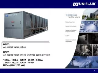
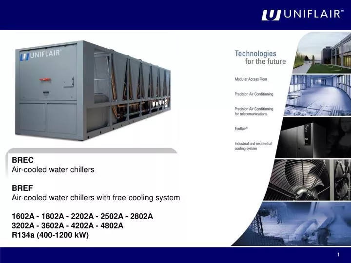
BREC Air-cooled water chillers BREF Air-cooled water chillers with free-cooling system 1602A - 1802A - 2202A - 2502A - 2802A 3202A - 3602A - 4202A - 4802A R134a (400-1200 kW). Serie BRE. Serie BRE.

E N D
BREC Air-cooled water chillers BREF Air-cooled water chillers with free-cooling system 1602A - 1802A - 2202A - 2502A - 2802A 3202A - 3602A - 4202A - 4802A R134a (400-1200 kW)
Serie BRE In BRE units, the inputs/outputs of the two circuits are divided into two boards connected with each other in a local area network. The two boards perform like a single controller to all intents and purposes. The microprocessor controller manages the unit’s operation autonomously. The microprocessor control boards contain the program and all the stored operating parameters which can be viewed and set on the user interface. LAN 11 LAN 1 LAN 21
Program Version By pressing the key, you can see the version of the control program burnt in the Flash EPROM. This information is essential when you want to add a new unit to a group of units connected in a Local Area Network because all the units connected with each other in a LAN must have the same software version. Also, when contacting a service centre, it is important to quote the version of the control program contained in the Flash EPROM accurately. Program Version BIGCH 4.2 15-07-10 SCREW 06ST021@L2042B2A00 Ver Date BIOS: 0422 00000 BOOT: 0000 00000 BREF 1602 No Pumps Comp.Fusheng R407C Mech.exp.Valve f 50 Hz
Language Selection Normally the display uses the language that has been defined by the regulation program selected in the Flash memory: IT = Italian, EN = English, DE = German, FR = French , SP = Spanish and the possibility of selecting a different language at any moment , by pressing + in the same time. . 12:22 26.3°C 55% Inizializzazione Attendere... LAN01 12:22 26.3°C 55% Initiating ... Please Wait LAN01 12:22 26.3°C 55% Einschaltung... Bitte warten LAN01 12:22 26.3°C 55% DEPART Attendre s.v.p. LAN01 12:22 26.3°C 55% Inicio Espere … LAN01 NOTE The only exceptions to this rule are the masks for service engineers ("Hardware Configuration"), which always appear in English language.
Serie BRE A B C When the unit is powered but not running, 3 fields are active on the user terminal display: 12:22 26.1°C EST Water OUT: °C 23.0 C A. Time and date (only in units featuring a clock card); B. Outlet water temperature; C. One of the following messages indicating what has switched the unit off: 1. ON/OFF button; 2. Remote control ; 3. Supervision system; 4. Timed switch-off - in units with clock card - indicating what time the next restart is programmed for; 5. Automatic unit inversion cycle; 6. Setback mode; 7. Forced switch-off subsequent to water flow alarm; 8. Forced switch-off subsequent to water flow alarm. To Start Unit Press On Key Warning : Stopped by Remote Control! Warning : Stopped by Supervisor ! Programmed Stop Restart at 13:15 LU Warning : Stopped on Standby ! Programmed Stop Press On Key Warning : Unit in Set Back Mode Warning : Stopped by Water Flow Alarm
Status screen with the unit running • When the unit is running, the STATUS SCREEN appears on the display • featuring 6 activefields: • Current time (only in units featuring a clock card), ambient • temperature. • B. Functions in progress; the following messages are given depending on the workingconditions: • • COOLING, HEATING, RECOVERY HEAT; • • PUMP-DOWN CIRC. 1, PUMP-DOWN CIRC. 2, PUMP-DOWN CIRC. 1-2; • • DEFROST CIRC.1, DEFROST CIRC.2, DEFROST CIRC.1-2; • • C.1 CONDENS LIMITS, C.2 CONDENS LIMITS, C.1-2 CONDENS LIMITS; • • C.1 EVAPOR LIMITS, C.2 EVAPOR LIMITS, C.1-2 EVAPOR LIMITS; • • C.1 COND.LOW PRESS., C.2 COND.LOW PRESS., C.1-2 COND.LOW PRESS.; • • C.1 DISCH.HIGH T., C.2 DISCH.HIGH T., C.1-2 DISCH.HIGH T. • • C.1 OIL LOW P., C.2 OIL LOW P., C.1-2 OIL LOW P. • • DRIPPING...,QUICK START • C. Where applicable, it indicates automatic cycle operation override: • • "MAN" in operating mode with manual control; • • "FORCE" when switching on using manual forcing; • • "WATCH" when the unit enters “setback mode” to keep temperature parameters within the set limits. • • "LOWPW" request for partial circuit operation to reduce power consumption (request from digital input)
Status screen with the unit running D. indicates unit’s slave status, which can be one of the following: • "ON": if the unit was switched on by the user teminal • "REMOTE": to a remote contact; • "SUPERV.": to a Supervisor; • "CYCLE": to automatic cycle inverting standard units and standby units; • "TIME": to a programme for operation based on time bands. E. indicates trouble status, which can be one of the following: • "ALARM" : when there is an alarm; • "SERV": when a meter totalling hours of operation exceeds the threshold. F. identifies with "LAN01", "LAN02", … when a number of units are connected in LAN. In this case, if a shared user terminal is used, it is possible to scroll among the units on the same LAN by pressing + keys at the same time. 12:22 26.1°C EST COOLING LAN 01 12:22 26.1°C EST COOLING LAN 02 ……
Hour-Meter Reading and Programming This part of the program is used to determine service intervals for the unit’s components: when the device in question exceeds the operating hours threshold indicated, the microprocessor reports the service request by activating the alarm condition and sending the “SERV” message up on the main form. There are also two forms featuring the number of times the compressor starts (with the option of resetting the count). The forms give the number of hours accumulated and operating thresholds. To edit limits and/or reset the hour-meter, you must call up the subroutine in programming mode. The functions regard the following unit components: 1. Compressors; 2. Water circulation pumps; 3. Compressors starting number; 4. Command manual Defrost circuit;
Hour-Meter Reading and Programming For each device, it is possible to: • read the accumulated number of hours of duty; • set operating thresholds (Note: by setting the threshold to 0, the counter is disabled); • reset the hour-meter (RESET = "OK"), e.g. once the component has been serviced and/or replaced. Parameters can only be edited within the permissible setting ranges. Screens on the left feature the progressive number of starts of the unit’s compressors and pumps, with the option of resetting the count.
Reading Input and Output States This part of the software, which can be called up directly by pressing the I/O key, allows to check the state of the board’s inputs and outputs. The codes given on the display are the same ones used to identify components in the unit and in the relevant literature (electrical and refrigerant drawings). DIGITAL INPUTS (ID1 - ID14): Remote On-Off = remote On-Off contact LP1 = circuit 1 low-pressure pressure switch AP1= circuit 1 high-pressure pressure switch TH1-2 = protector breaker compressor 1 TH3-4 = protector breaker compressor 2 THPE1 = thermo protectors for the water circulation pump RSF = phase sequence relay FS = water flow-switch Heat Rec Req = start up contact of heat recovery THPES = thermo protectors for the water circulation pump Free-Cooling Change SETP. = commutation contact for the working setpoint Power Reduc. = reduction contact of the absorbed power Rem. SUM/WIN = commutation contact for SUMMER/WINTER operation I.V.LimitSw.= contact switches valve Free-Cooling Compress.1 Integral Prot. = KRIWAN protection for compressor 1
Reading Input and Output States ANALOGUE INPUTS (B1 - B8): Supplies the readings of the TEMPERATURE and PRESSURE sensors connected to the board. UpCOe Expansion Analogue inputs (B1 – B4) Supplies the readings of the sensors connected to the UpCOE expansion board. B1 = Rem Offset summer setpoint ANALOGUE OUTPUTS DIGITAL OUTPUTS (C1 - C13): V3V1 (recovery) = 3-way valve 1 contact VIC1 = cycle inversion valve circuit 1 CPE1 = pump contactor circuit 1 CC1,CC2,CC3 = compressor contactors ETVR1 (recup.) = ECO system or liq. inject. system switch-on CPES = free-cooling pump contactor Al. type “A” = digital outputs of signaling alarm the type “A” ETF1 = circuit 1 freon solenoid valve ETVC1 (rec.) = circuit 1 condensing valve CV1R/CV1D = fan 1 contact Al. type “B” = digital output of signalling alarm the type “B” ANALOGUE OUTPUTS (Y1-Y2) Y1 Fan 1 Signal = fan speed control; Y2 Anaout 2 = free-cooling valve contact.
Reading Input and Output States INPUT/OUTPUT TABLE FOR THE TWO UpCO1m BOARDS
Reading Input and Output States INPUT/OUTPUT TABLE FOR THE TWO UpCO1m BOARDS
Configuring the unit Unit’s configuration mode is accessible by keeping pressed the P programming key until you hear a short audible signal and then pressing the I/O key. Once you have entered the password (by factory: 121), the relevant form is called up, comprising three options: move the cursor vertically to the line you are interested in using the DOWN key and then call up the forms by pressing the ENTER key. HARDWARE CONFIGURATION: The unit control program needs to be “configured”, i.e. adapted to the unit it is installed in. During this stage, you must define all elements making up the unit that the microprocessor will be required to control. This operation is generally only required when the controller is installed actually on the unit, in which case, therefore, it is performed at the factory during final testing. Nonetheless,. configuration may be required as a result of later changes made to the unit Consequently, forms concerning configuration appear in English and are intended for use by service engineers only.
Configuring the unit • DEVICES CONNECTED TO THE UNIT: • Allows to set: • • set unit type depending on whether the unit in question is a: • - standard-version chiller • - chiller with condensation heat recovery • - chiller with free cooling • • Circulating pumps • • Fan speed regulation • Only some of the following forms will be displayed, depending on the type of unit. • SIZE AND DEVICES CONFIGURATION • Allows to set: • - the size of the unit • - the typeofcompressors • the typeoffans UNIT Type: STD Chiller Circul Pumps: 2 Fan Speed Regul: Y Unit Size: 1602 Compressor Type: Fusheng Fans Type: STD
Configuring the unit • CONFIGURATION OF SCREW COMPRESSORS’ OPTIONS • Allows the following options to be set: • • Injection of liquid for additional cooling only necessary for high levels of compression (Bitzer Compressors); • • Eco+Subcooling to obtain an increased sub-cooling of the liquid (available for both Bitzer and Fusheng compressors). • CONFIGURATION OF THE ELECTRONIC EXPANSION VALVE • Allows to set: • - the type of refrigerant gas • - high temperature function • - the presence of the electronic expansion valve • the type of electronic expansion valve • COOLING SETPOINT LIMITS • Allows the minimum and maximum setpoint limits to be set.
Configuring the unit PUMP-DOWN CONFIGURATION: Allows pump-down mode to be activated and the maximum time for the procedure to be set. FREQUENCY OF THE ELECTRIC NETWORK: This Screen allows the frequency of the electric network. FAN REGULATION - STANDARD MODE: This Screen allows the fan modulation parameters to be set on the basis of the condensing pressure: by disabling the low-noise mode, the fan speed regulation on a 2 steps regulation, as illustrated in the diagram below.
Configuring the unit FAN REGULATION - LOW NOISE MODE: By enabling the low-noise mode, the fan speed regulation is based on a ramp of 3 steps. The Screen on the left allows the parameters related to the 2nd modulation step.
Configuring the unit MAXIMUM SPEED SETPOINT OF FANS IN FC MODE Screen 72 in the event of total free-cooling, allows the maximum fan speed to be set. SETPOINT FREE-COOLING ACTIVATION In free-cooling units, this Screen appears which enables the activation delta T to be set. When the external air temperature is lower than the inlet water temperature, the unit enters free-cooling mode: the water circulation pump activates by means of the free-cooling coil and the compressor steps change in order to increase the efficiency of the air-water exchanger.
Intelligent Free-Cooling FREE-COOLING ACTIVATION WITH UNIT IN STAND-BY This Screen allows the intelligent free-cooling management to be activated. The hydraulic connections among chillers are required, as shown below. THE IDEA OF THE INTELLIGENT FREE-COOLING: exploiting the air/water exchangers of the unit/s in stand-by
Intelligent Free-Cooling Direct expansion mode
Intelligent Free-Cooling Mixed mode
Intelligent Free-Cooling Free-cooling mode
Intelligent Free-Cooling In the diagram shown below, an example is shown where unit 1 is in stand-by and units 2 and 3 are running and connected with intelligent free-cooling. If the external temperature is able to activate the free-cooling, the control system of the units running, controls the start-up of the fans of the unit in stand-by (1) and the start-up of the free-cooling pump (C) of the units which are running (2 and 3). In this way the water is sent to all of the available free-cooling coils.
Intelligent Free-Cooling Units without onboard pump/s
Intelligent Free-Cooling Units with onboard pump/s
Configuring the unit ISOLATING VALVE This mask gives the possibility to manage an external motorized valve (at customer care) for the main water circuit. NOTE: The installation of this valve is strictly recommended when there are external main water pumps. • There are two different ways to manage this valve: • Use the limit switch of the valve. In this case you can set a time within which the valve must be closed; if the valve doesn’t close its contact within this time, you get the alarm: • Do not use the limit switch of the valve. In this case you can set a time which must take into account the time needed for the valve to be fully open; after this timing, the main pump is switched on. You don’t get any alarm regarding the valve. Alarm Isolating Valve Not (Fully) Opened:Check Valve/LimitSwitch
Configuring the unit ANTI-FREEZE – ACTIVATION OF THE FC PUMP: This Screen gives the possibility to activate the circulation pump through the free-cooling coils in anti-freeze operation. If this function is activated in the standby unit, the FC pump is switched on as soon as the external temperature falls below 1,0°C; it turns off when it rises above 3,0°C. N.B.: Only a correct mix of glycol ensures that the coils do not freeze if the external temperature falls below zero: the function indicated cannot guarantee the integrity of the coil, above all in freezing temperatures. REGULATION OF THE AMPEROMETRIC SENSORS This mask defines the working range of TA1 and TA2. These thresholds and the multiplying factor change accordingto the type of compressor.
Configuring the unit MAXIMUM ABSORBED CURRENT REGULATION This screen allows the maximum absorbed current threshold of the compressor above which the cooling capacity is reduced. Usually it matches the FLA of the motor.
Configuring the unit READING RANGE REGULATION This screen allows the reading range of the high pressure transducer to be set. READING RANGE REGULATION This screen allows the reading range of the low pressure transducer to be set. SENSOR ADJUSTMENT This screen and the following Screens allow the temperature sensors which can be found in the unit to be adjusted (“read value”), when there is a difference between the value measured by the probe and the actual temperature, measured by a precision instrument. MONITORING OF THE REFRIGERANT LOAD This mask is managed by an algorithm which constantly monitors the sub-cooling value for both circuits. NOTE: the liquid temperature sensors are optional.
Configuring the unit REMOTE SETPOINT Screen 88 allows the relative control parameters of the remote modulating control of the unit operating values to be set. A high-precision (1/1000) 20Kohm resistor must be connected in series to terminal B1 the UpCOE board. Next, apply the 0-10V signal referred to the GND terminal (both terminals are located on the control card). The zero value is adjusted automatically using the “Hardware setup” function. HEAT RECOVERY Screen 89 allows the maximum condensation temperature limit to be set above that which is prevented by the heat recovery. OPTIONAL REMOTE SETPOINT This mask means that, if presence of a LAN connection, the changing in the set-point is sent through the LAN; it is enough to install the contact for the changing in set-point in one unit only and then to enable this function.
Configuring the unit HeatRecovery Cond.Pressure Limit 60°C This mask allows to set the maximum pressure at which the heat recovery will be disabled. It is possible to set the automatic or manual reset for the flow switch alarm. If set to automatic, it is possible to decise how many times (from 1 to 4) the alarm will be in automatic reset; after the this number of pre-alarms (within a time interval of one hour) the alarm becomes critical and stops the unit. It is then necessary a manual reset. In case of a UPS power supply for the controller, it is necessary to enable this function in order to disregard some alarms which could appear because of the missing main power line. It takes the information from the RSF. Water flow-Sw.Alarm Reset: A Double Power Supply N
Configuring the unit • QUICKSTART • This mask allows the Quick-Start function to be activated. If, following a return of supply (Power ON) the temperature of the water is above the summer SetP.+ the programmed set, the compressors will start-up in approx. 3 minutes, reducing all the standard timings. • BUZZER ACTIVATION TIME • This screen allows the maximum activation time of the buzzer activation when an alarm is active to be set. • SETTING THE ACCESS PASSWORDS • This screen allows the access passwords to be set: • - SETTINGS MENU is accessible with the default password “00000” • SERVICE MENU is accessible with the default password “00121” • Both passwords can be changed and it is recommended to write the new passwords down before changing the existing ones. • If the passwords have been lost, the access to SERVICE MENU is granted with password “00242”.
Configuring the unit PROGRAMME SETUP This operation is performed automatically if the programme is replaced. It may prove useful if you find data (setpoints, configurations etc.) are “contaminated” as it allows you to clear the memory (including data concerning the unit’s HARDWARE configuration): all setpoints are automatically restored to their respective factory settings (see section entitled "DEFAULT VALUES"). Following this operation, the controller must be reconfigured and you will need to adjust any setpoints that are to have a value other than the default value. AL. PAGE CLEAR-UP By clearing the alarm log, you erase the all alarm events stored in the memory. HARDWARE SET-UP Used to run an automatic procedure for detecting devices connected to the controller. This operation is useful when you want to add an option to the card, replace a sensor, or when the display features the "NC” message instead of the temperature sensor’s reading.
Delay Settings This screen concerns initial transient behavior and gives you the option to set: • delay before the unit restarts after a power cut (‘POWER ON DELAY’) - it is required to prevent simultaneous starts in multiple installations; in LAN-connected units, a progressive start sequence (unit 1, unit 2, …) is run automatically, with 5-second intervals between one unit and the next. • initial period - from when the compressor starts - during which the low-pressure switch reading is disregarded (‘LP-STAT DELAY’). It enables the compressor to start even in a harsh climate. • length of time between the unit switching on and control starting (‘START TRANS.’) - this is the initial period deemed necessary to give the control system time to stabilize. During this period, the FS water flow-switch reading is also disregarded. This allows the unit to start without generating the "Loss of Water Flow" alarm. • delay - from when the unit starts - before environmental condition alarms are reported (‘T Al Delay’).
Delay Settings • This Screen allows the anti-hunting time constant to be set to avoid excessive differences in temperature. The greater the heat inertia of the water circuit, the greater this value must be set. • This Screen allows the water flow-switch (FS) parameters to be set: the first parameter is the acquisition delay for the signal issued by the flow-switch when the unit is started, whilst the second parameter is the length of the delay before the alarm, if there is one, is reported after the pump starts. Lastly, the third parameter (only displayed if there are two pumps) is the rotation time for the pumps’ operation. • This Screen allows the compressor timing to be set: • minimum time between two starts for a single compressor; • minimum time each compressor stays on; • minimum time each compressor stays off; • minimum time between two consecutive starts by different compressors; • This screen allows the start-up delay of the free-cooling pump during opening of the water isolation valve to be set.
Manual Control • During regular operation, all components the unit is fitted with are managed automatically. Nonetheless, to make maintenance and adjusting work easier, or if there is an emergency, individual components can be switched on using the manual override feature, regardless of the control process. • In particular, it is possible to: • switch the unit on/off in manual mode; • switch the compressors on/off; • swap the two pumps over; • switch on /off the FC pump; • control the ramp for the fans’ modulating control. • The safety devices are always activated, also during manual operation.
Manual Control To alter the operating mode of a component, simply move the cursor onto the relevant line, press the UP or DOWN key to change from automatic ("No") to manual ("Yes") or vice versa, and confirm by pressing the ENTER key. While using Manual Override mode, to start one or more devices, the label “MAN” will be displayed in the main mask.
EXV Parameters The Screens shown on the left allow the read only data and some operating parameters of the electronic expansion valve on circuit 1 to be displayed. The screens are the same for the valve on circuit 2, but it is necessary to enter the screen dedicated to “Circuit 2 Valves”
EXV Parameters This Screen allows the type of electronic expansion valve to be set. Allows the superheating value to be set in the various operating modes. Allows the Proportional Gain to be set in the various operating modes. Allows the set point for the Integral Time to be set for different operating modes. Allows the set point of the Derivative time and the maximum suction temperature to be set.
EXV Parameters Allows the maximum number of opening steps and the set point of the neutral band for the superheating. Allows the relationship in % of the power of the electronic expansion valve and the cooling circuit to be set where it has been inserted in the various operating modes described. These Screens allow the limits of low superheating to be set: integral time and temperature in the various operating modes.
EXV Parameters Allows the setpoints of the MOP and LOP to be set in chiller mode. Allows the start up delay of the MOP and the integral time to be set. Allows the integral time of the LOP to be set. Allows the start and finish of the range of the evaporating pressure sensor to be set. Allows the delay time regarding the activation of the following parameter alarms to be set : Low subcooling, high suction temperature, LOP and MOP. Allows the delay time regarding the activation of the “Pressure sensor failure” to be set for the compressor start-up and during normal operation.
Remote Control and LAN Settings As an alternative, the unit can be started and stopped by means of: 1. a remote contact (or "remote control"); 2. a "supervision system" connected to the microprocessor with a serial cable. The microprocessor nonetheless retains control of the unit’s resources. ON/OFF VIA REMOTE CONTACT: the closing of a remote contact is responsible for starting the unit. The N.O. contact is voltage-free and connected to the master card (see wiring diagram). In units with a standard control programme, digital input 1 is the one specifically used for the on/off contact. SUPERVISION SYSTEM: a supervision system exchanges data via a serial cable with the unit’s master card, which is controlled and monitored from a remote location. An optional Serial Card is available for this purpose, used to enable optoisolated interfacing with an RS-485 network for data transfer.
Remote Control and LAN Settings This Screen allows to establish whether the unit is slaved to a remote control. More specifically, you can set: • the remote on/off command via clean contact (‘I/O via Contact’); • the remote on/off command from a supervision system by means of RS-485 serial line (‘I/O via Serial’). Being mutually exclusive, if the setting is "I/O via Serial Yes" , the "I/O via Contact" option is automatically disabled. • Moreover, with Screen 140 it is possible to set (only in heat pumps) the activation of the SUMMER/WINTER changeover remotely by means of a contact connected to the digital input 14 (see the electrical diagram attached to the unit).
Remote Control and LAN Settings • SETTING TRANSMISSION PARAMETERS FOR SUPERVISION: • Allows the basic parameters to be set (first three lines) for switching via supervision, i.e. • serial address of the unit connected to the serial supervision network (must match serial address set in supervision program); • data transfer rate (Ser. speed): 1200, 2400, 4800, 9600 and 19200 for RS-485. • protocol type (standard or Modbus). • In addition, the fourth line (should the unit be ready for connection in a Local Area Network) is for setting the number of units connected in the LAN. • Remember that to prepare the unit for connection in a LAN, it must be assigned a LAN address other than 0 as indicated in the relevant LAN guide.
Remote Control and LAN Settings This Screen concerns parameters for automatic rotation between running units and standby units. Via said form, you can determine: • whether to activate this management feature (Yes/No). When automatic rotation is enabled, you have to press the ON/OFF key on the unit with the lowest address in the network. • automatic cycle time between one inversion and the next (‘CYCLE TIME’) - if it has the value zero (" 0 "), the controller runs a test, rotating units at two-minute intervals. • the number of units on standby (‘Num. UNIT STAND-BY’). Automatic rotation can be executed: • on a time basis (based on the above-mentioned cycle-time); • subsequent to a level-2 alarm, i.e. subsequent to an alarm for which AR or BR has been set in the alarm addressing forms (see relevant section herein).
Remote Control and LAN Settings • This Screen, which is only seen if the local network is configured, allows the temperature regulation to be set in three different ways: • Independently: the unit independently controls the water temperature regulation; • Connected: the unit control carries out the water temperature control by calculating the average temperature of the units which are operating; • Cascading: the control carries out an off-set on the regulation set point according to the units connected in the network therefore allowing the units to be switched on in succession. Each unit maintains its own regulation timings.