Download

1 / 21
240 likes | 459 Views
TRANSILVANIA UNIVERSITY OF BRA Ş OV FACULTY OF ELECTRICAL ENGINEERING AND COMPUTER SCIENCE – Master SEA. CONTROL STRATEGIES FOR GRID CONNECTED INVERTER IN DPGS APPLICATIONS -DISSERTATION-. Coordinator: Lecturer Dr. Eng. Luminita BAROTE. Student : Eng. Banica Ana-Maria Gr. SEA 4706.

E N D
TRANSILVANIA UNIVERSITY OF BRAŞOVFACULTY OF ELECTRICALENGINEERINGAND COMPUTER SCIENCE – Master SEA CONTROL STRATEGIES FOR GRID CONNECTED INVERTER IN DPGS APPLICATIONS -DISSERTATION- Coordinator: Lecturer Dr. Eng. Luminita BAROTE Student: Eng. Banica Ana-MariaGr. SEA 4706
Content • Project goal • Model description • PV Panel Model • Control Structures • Current controllers • Grid Synchronization • Zero crossing detection method • Phase – Look - Loop Technique • Simulation results • PR control in single-phase system connected to the grid • PR control in three-phase system connected to the grid • Conclusions
Project goal The goal of this project is to study, analyze and simulation the control of a small photovoltaic system connected to the grid. Purpose of this study: • Implement MPPT control for single-phase inverter control using P & O algorithm; • Grid synchronization algorithm using ZCD method and PLL technique; • Model validation used in the control strategy and results revealed using trial and error method.
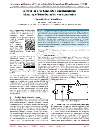
Model description The analyzed system is compose of the PV generator, converter, LC filter, transformer, grid and the most important the control block.
The I-V and P-V characteristic of the HDSM-255P PV panel at different temperatures and irradiation
Current controllers PI Controllers PR Controllers the complexity of the calculations will be reduced a good harmonic compensators PR can be used to eliminate the problems of the PI the PR controller is defined as: the harmonic compensator is defined as: • reduce the harmonic distortion • poor disturbance • a poor THD of the current will typically be obtained • the form of the PI is defined as:
Grid Synchronization Zero crossing detection (ZCD) method • is a simple method for estimating the phase angle of the network by detecting the voltage waveform at zero crossing; • this method has a slow dynamic response. Phase Look Loop technique • is a phase tracking algorithm able to provide an output signal synchronized with the input of the reference system for frequency and phase variables; • is an algorithm suitable for systems connected to the national network.
Grid current waveform and THD representation with and without HC(THDu=0%)
Grid current waveform and THD representation with and without HC(THDu=2%)
Grid current waveform and THD representation with and without HC(THDu=8%)
PR control in three-phase system connected to the grid In order to testing the PR control have performedsimulations in the following cases: • Case I : P = 2000 [W] and Q = 0 [Var]; • Case II : P = 2000 [W] with step at 0.7 [s] and Q = 0 [Var]; • Case III : P = 1500 [W] and Q = 1000 [Var]; • Case IV : P = 1500 [W] and Q = -1000 [Var].
Conclusions • This project presents a current control method considering harmonics compensation and two robust synchronization methods in single-phase and three-phase grid connected inverters. • The configuration was modeled and simulated in Simulink. • The simulation results show that the proposed control method (PR current controller without/with HC and a PLL+ZCD) is effective for DPGS applications and in our configurations a better energy quality (IEEE 1547.1) delivered to the grid with PR proportional gain set at Kp=10, Ki=150 is obtained.