Download
1 / 16
170 likes | 410 Views
Grid Generator in ANSYS. 58:110 Computer-Aided Engineering Spring 2005. Department of Mechanical and industrial engineering February 2005. Topics. Running ANSYS Geometry Model Prepare before Meshing Meshing methods Free/Automatic meshing Mapped meshing

E N D
Grid Generator in ANSYS 58:110 Computer-Aided Engineering Spring 2005 Department of Mechanical and industrial engineering February 2005
Topics • Running ANSYS • Geometry Model • Prepare before Meshing • Meshing methods • Free/Automatic meshing • Mapped meshing • Sweep meshing • Checking
Running ANSYS To run ANSYS: Login any ICAEN PC with WIN XP Start -> All Programs -> Engineering Software -> ANSYS 8.1
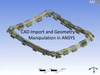
Geometry Model Import form Pro/E: File -> Import -> IGES
Geometry Model • Simple Geometry Can be generated in ANSYS too. • Goto ANSYS Main Menu • Preprocessor -> Modeling->Create • ->Operate • ->Modify/Move • ->Copy • …….
Prepare Before Meshing • Check Geometry • Check geometry carefully. Make sure there is no gap, overlap, broken line/area/volume. • Set Element Type • Goto ANSYS Main Menu • Preprocessor -> Element Type -> Add/Edit/Delete • Select the appropriate element type
Meshing methods - Free Meshing • Free meshing has no limited by shape and pattern. • Only available for 2D quadrilateral/triangular element shapes and 3D tetrahedral elements • It is easy but for complex geometries can often lead to distorted elements that undermine accuracy. • Meshing Commands Goto ANSYS Main Menu Preprocessor -> Meshing ->Mesh Attributes -> Mesh tool -> Size Cntrls ………………
Free Meshing MeshTool -> Check SmartSize, select 6 (1 to 10: From Fine to Coarse) -> Mesh: Volumes Shape: Tet and then Mesh Want to refine mesh (supposed at the bottom): -> Refine at, Elements and then Refine Box select the elements around the bottom area and select the refine level (1 to 5: min to max) 3 Circle select the elements around the hole and select the refine level (1 to 5: min to max) 2 Then apply.
Free Meshing Original Mesh After refinement
Free Meshing Uniform mesh in one volume (Size control) MeshTool -> Uncheck SmartSize -> Size controls: Global -> Set Global Element Sizes ->Size Element Edge Size 5 and then Mesh
Mapped Meshing • Mapped meshes are easier to control and offering more accurate • User should specify the size and shape of the meshes in local regions • Before use the Mapped meshing, the regions should satisfy: • 2D - each aea must be 4 / 3 sided, that is the area should be made up of 3 or 4 lines/curves • 3D – each volume must have 6 faces
Mapped Meshing Procedure 1. Partition the non 6-faced volumes Preprocessor->Modeling->Operate->Divide: Volu by WrkPlane 2. Mapped Meshing MeshTool -> Uncheck SmartSize -> Size controls: Global -> Set:Global Element Sizes ->Size Element Edge Size: 5 -> Mesh: Volumes Shape: Hex: Mapped and then Mesh
Mapped Meshing Mapped mesh in all volumes Partition of solid model
Sweep Meshing Sweep Meshing is usually used to match volumes with different mesh shapes and densities. So it is less control like free mesh. MeshTool -> Uncheck SmartSize -> Size controls: Global -> Set: Global Element Sizes ->Size Element Edge Size: 5 -> Mesh: Volumes Shape: Hex/Wedge: Sweep Auto Src/Trg and then Mesh
Checking Mesh • After meshing, make sure checking your mesh with some criteria. • IN ANSYS, using the following two: • Element distortion (checked by the angle) • Element connectivity • ANSYS Main Menu: • Preprocessor->Meshing • ->Check Mesh ->Individual Elm • ->Connectivity