Download
1 / 26
260 likes | 350 Views
Understand concepts of circuit and packet switching, difference between logical and physical channels, and evolution towards packet switching for faster, more efficient data communication. Know the benefits and drawbacks of message and packet switching methods.

E N D
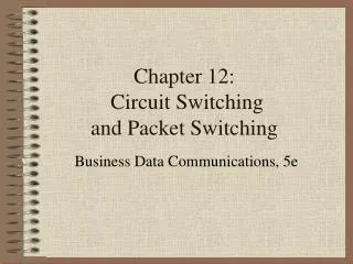
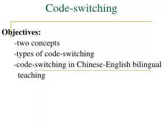
Contents • Circuit Switching v/s Packet switching • Logical Channel v/s Physical channel • Statistical Time Division Multiplexing • Connectionless and Connection Oriented Data Communications
Switching Message Switching Circuit Switching Packet Switching Datagram Approach Virtual Circuit Approach SVC PVC Switching Methods
A B D C B A D C B A S C D Direction of transmission Circuit Switching A S D C B A D C B Physical Channels (Time Slots)
A B - - - A - - - A S C D Direction of transmission Circuit Switching A S - - - A - - - Inefficient Utilization of media
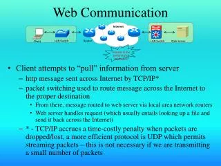
DATA Time All Communications are bursty Request for some website home page Data transfer from the web site
Message Switching • Store and Forward technique • Send the message to next node • Next node stores it in memory • It takes a decision about the next hop closer to destination • Forwards it to next hop when link to the next hop is available and next node is ready to receive it • Next hop repeats the same process • Message finally reaches its destination node
M1 M1 M1 M1 D A Store & Forward Store & Forward Store & Forward Store & Forward E B M2 M2 M2 Message Switching
Message Switching • Messages are bigger in size • Storage and processing requires more resources • Sometimes nodes may not have sufficient resources • Messages remain stored in memory of a node for longer period • Entire process becomes slow • Error will require full message to be retransmitted • Suitable for services like Telegraphs etc • Not suitable for fast modern networks
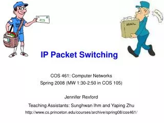
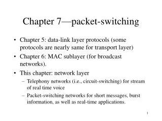
Evolution of Packet switching • Break the message into smaller packets • Transmit the packets hop by hop to destination • Destination reassembles packets into original message • Requires less resources at nodes • Process becomes faster compared to message switching • Error requires only retransmission of errored packet not the full message
D B A Packet Switching: Statistical Multiplexing A B D B A C D Direction of transmission Virtual Channels No Physical channel like a Time Slot
Packet Switching • Allot Bandwidth on Demand • Buffer Data and allow bandwidth to only those hosts which have data to transmit. • To the data, add some delimiters to indicate end of data transmitted by a particular host. • Add some tags (addresses or channel identifiers) to indicate the sender.
FFFFFF C F B F A F F: A flag to delimit the data transmitted by one host A, B, C: Identifier for the transmitting host (Address or Virtual channel no.) Packet Switching A B D B A C D Direction of transmission FFFFFF101010CF001010101110BF101111011AF
Packet Switching A B C A C D Direction of transmission FFFFFF101010CF00101010111010101111011AF C is denied the opportunity to transmit
Packet Switching A B C A C D Direction of transmission FFFFFF101010CF00101010111010101111011AF 1 1 1 1 1 The whole data for A is retransmitted
Packet Switching A B C A C D Direction of transmission FFFFFF101010CF00101010111010101111011AF Solution is break data into small blocks PACKETS
Packet Switching Techniques • Connection Oriented • End to end path is setup before any data communication happens • Every packet need not carry the destination address • Destination address is send to the network only once during the call setup process • Connectionless • Path setup is not required. Drop the packet in network and network takes it to destination • Every packet should must carry the source and destination address • Every packet is examined independently by the nodes for its routing
Connection Oriented Data Communications • A path is established before actual data transfer. • All packets take the same path. • Routing decision is taken before actual data transfer. • Actual data packets contains the routing labels. • All packets follow the same path • Packets reach its destination in sequence • Disruption in communication if link fails during data transfer. • Quality of service can be guaranteed. • Example X.25, Frame Relay, Asynchronous Transfer Mode(ATM).
1 49 3 35 . . . . I/C I/C I/C I/C O/G O/G O/G O/G P P P P CHL CHL CHL CHL P P P P CHL CHL CHL CHL 1 5 3 7 2 7 5 20 1 20 2 49 Connection Oriented Data Communications 2 3 4 2 1 3 2 4 1 5 1 3 2 1
B B A A C C Routing Table I/c O/g P Chl P Chl Connect B Chl No.1 Connect C Chl No.2 A 1 B x A 2 C y F F Virtual Channel 1001010110F010101001F 10 01
4 4 3 3 2 2 1 1 4 3 2 1 2 2 2 2 1 1 1 1 Permanent Virtual Circuit-PVC
4 4 3 3 2 2 1 1 4 3 2 1 2 2 2 2 1 1 1 1 Switched Virtual Circuit-SVC
Connectionless Data Communications • A path is not established before actual data transfer. • All packets do not take the same path • Routing decision is taken on the arrival of every packet at every node. • Every packet contains the full destination address. • No disruption in communication if link fails during data transfer and an alternate path exists. • Quality of service is not guaranteed. • Packet can follow different path • Packet can arrive out of sequence at destination • Example Internet
Routing Table Dest. Next Hop Connectionless Data Communications Packet 1 Packet 2
2 1 1 1 1 4 3 2 1 3 1 4 3 3 3 1 1 4 4 2 2 2 3 4 1 4 1 2 1 2 4 2 2 Datagram Approach
Thank you Questions?