Download
1 / 21
210 likes | 286 Views
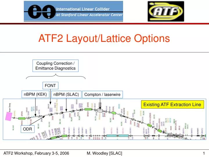
ATF2 Layout/Lattice Options. Coupling Correction / Emittance Diagnostics. FONT. nBPM (KEK). nBPM (SLAC). Compton / laserwire. Existing ATF Extraction Line. ODR. “Optimal” Layout (from ATF2 Proposal vol. 1). ~8 m wall to IP. Assembly Hall. chicane. 8.3 m wall to dump face

E N D
ATF2 Layout/Lattice Options Coupling Correction / Emittance Diagnostics FONT nBPM (KEK) nBPM (SLAC) Compton / laserwire Existing ATF Extraction Line ODR M. Woodley [SLAC]
“Optimal” Layout (from ATF2 Proposal vol. 1) ~8 m wall to IP M. Woodley [SLAC]
Assembly Hall chicane 8.3 m wall to dump face (14.3 m wall to IP) M. Woodley [SLAC]
β*x,y = 4,0.1 mm 30 cm offset M. Woodley [SLAC]
new quadrupole QMX (between QF3X and BH1X.3) M. Woodley [SLAC]
EXT Skew Correction & Emittance Diagnostic Section (optimal2) SQ SQ SQ SQ WS WS WS WS WS 1.0 1.0 1.0 0.7 0.7 0.7 0.7 1.0 1.7 1.0 3.0 3.0 3.0 – x – y 90° 90° 180° 90° 90° 90° 55° 25° 41° 31° 31° 41° 26° 26° 34.1 8.6 136.3 6.2 80.4 10.5 136.3 6.2 80.4 10.5 σ (μm) 4 < σx/σy < 22 M. Woodley [SLAC]
TABLE 1: existing ATF EXT quadrupoles ------------------------------------------------------------------------------ power supply maximum currents from N. Terunuma email (April 22, 2005) ------------------------------------------------------------------------------ a note on names: the "quad name" column names the location in the beam line; the "magnet name" column names the physical magnet that presently resides at each location; the "power supply" column names the power supply whose cables come to that location ------------------------------------------------------------------------------ quad magnet magnet power Imax KLmax notes name name type supply p.s. @ 1.3 GeV ----- ------- ----------- ------ ---- --------- ------------------------ QD1X QD1Xmag Hitachi 2 QD1Xps 100 0.6657 QD2X QD2Xmag Hitachi 2 QD2Xps 100 0.6657 QF1X QF1Xmag Hitachi 2 QF1Xps 100 0.6657 QK0X QK0Xmag ECUBE skew QK0Xps 20 2.7673e-4 QS1X QS1Xmag ECUBE skew QS1Xps 20 2.7673e-4 QF2X QF2Xmag Hitachi 1 QF2Xps 100 0.2989 QD3X QD3Xmag Hitachi 5 QD3Xps 100 2.1050 QF3X QF3Xmag Hitachi 5 QF3Xps 100 2.1050 QF4X QF4Xmag Hitachi 5 QF4Xps 100 2.1050 QS2X QS2Xmag ECUBE skew QS2Xps 20 2.7673e-4 QD4X QD4Xmag Hitachi 5 QD4Xps 200 2.1050 use Imax = 100 amps QD5X QD5Xmag Hitachi 5 QD5Xps 100 2.1050 BH4X ....................................................................... QF5X QF5Xmag Hitachi 5 QF5Xps 100 2.1050 QK1X QK1Xmag IDX skew QK1Xps 5 2.5363e-2 QD6X QD6Xmag Tokin 3393 QD6Xps 100 0.3021 QK2X QK2Xmag IDX skew QK2Xps 5 2.5363e-2 QD7X QD7Xmag Hitachi 5 QD7Xps 100 2.1050 QK3X QK3Xmag IDX skew QK3Xps 5 2.5363e-2 QF6X QF6Xmag Hitachi 5 QF6Xps 100 2.1050 QK4X QK4Xmag IDX skew QK4Xps 5 2.5363e-2 QD8X QD8Xmag Hitachi 4 QD8Xps 200 2.0650 QF7X QF7Xmag Hitachi 4 QF7Xps 100 1.0488 QD9X QD9Xmag Hitachi 4 ------ --- 2.0650 in series with QD8X magnetic measurements data file Imax ------------------------------- ----- ATF$MAG:MAG_KI_Q_HITACHI_1.FOR 140.2 ATF$MAG:MAG_KI_Q_HITACHI_2.FOR 100.2 ATF$MAG:MAG_KI_Q_HITACHI_4.FOR 200.4 ATF$MAG:MAG_KI_Q_HITACHI_5.FOR 100.6 ATF$MAG:MAG_KI_Q_TOKIN_3393.FOR 139.0 ATF$MAG:MAG_KI_Q_IDX_SKEW.FOR 20.0 ATF$MAG:MAG_KI_Q_ECUBE_SKEW 20.0 M. Woodley [SLAC]
TABLE 2: ATF2 EXT quadrupoles ("optimal 2") ------------------------------------------------------------------------------ quad magnet magnet power Imax KLmax KL NOTEs name name type supply p.s. (see below) ----- ------- ---------- ------ ---- --------- ------- ---------------- QD1X QD6Xmag Tokin 3393 QD1Xps 100 0.3021 -0.2500 2 QD2X QD2Xmag Hitachi 2 QD2Xps 100 0.6657 -0.2529 QF1X QF1Xmag Hitachi 2 QF1Xps 100 0.6657 0.3554 QK0X QK0Xmag ECUBE skew QK0Xps 20 2.7673e-4 0.0 QS1X QS1Xmag ECUBE skew QS1Xps 20 2.7673e-4 0.0 QF2X QF2Xmag Hitachi 1 QF2Xps 100 0.2989 0.2122 QD3X QD3Xmag Hitachi 5 QD3Xps 100 2.1050 -0.5507 QF3X QF3Xmag Hitachi 5 QF3Xps 100 2.1050 0.3238 QMX QF5Xmag Hitachi 5 QF5Xps 100 2.1050 0.7293 3 QF4X ------- IHEP ------ 100 2.5 2.0628 1,4 QS2X QS2Xmag ECUBE skew QS2Xps 20 2.7673e-4 0.0 QD4X QD4Xmag Hitachi 5 QF7Xps 100 2.1050 -1.3399 5 QF5X QD5Xmag Hitachi 5 QD5Xps 100 2.1050 0.6193 BH4X ....................................................................... QD5X QD1Xmag Hitachi 2 QD6Xps 100 0.6657 -0.3528 2 QK1X QK1Xmag IDX skew QK1Xps 5 2.5363e-2 0.0 QD6X QD7Xmag Hitachi 5 QD7Xps 100 2.1050 -1.2504 QF6X QF6Xmag Hitachi 5 QF6Xps 100 2.1050 1.2504 QK2X QK2Xmag IDX skew QK2Xps 5 2.5363e-2 0.0 QD7X QF4Xmag Hitachi 5 QF4Xps 100 2.1050 -1.2504 QF7X QD8Xmag Hitachi 4 QD8Xps 200 2.0650 1.6706 6 QD8X QF7Xmag Hitachi 4 QD4Xps 200 2.0650 -1.2478 5 QF8X QD9Xmag Hitachi 4 ------ 200 2.0650 1.6706 6 QK3X QK3Xmag IDX skew QK3Xps 5 2.5363e-2 0.0 QD9X ------- IHEP ------ 100 2.5 -1.2504 1 QF9X ------- IHEP ------ 100 2.5 1.2504 1 QK4X QK4Xmag IDX skew QK4Xps 5 2.5363e-2 0.0 QD10X ------- IHEP ------ 100 2.5 -0.8436 1 QF10X ------- IHEP ------ 100 2.5 0.8106 1 QD11X ------- IHEP ------ 100 2.5 -0.3753 1 QF11X ------- IHEP ------ 100 2.5 0.3753 1 QD12X ------- IHEP ------ 100 2.5 -0.3753 1 note: IHEP quadrupole may need > 100 amps to reach KL = 2.5 M. Woodley [SLAC]
NOTEs: a) the names in the "quad name" column of TABLE 2 should be considered arbitrary; in some cases existing EXT quads were not moved or reconnected but were renamed b) quad center locations upstream of BH4X are unchanged (except for new quad QMX); the quad support stands are also unchanged since only quads with identical core lengths (but different number of coil turns) have been "swapped"; all quads downstream of BH4X have been moved c) the Hitachi Type 2 and Tokin 3393 quads are 6 cm core magnets ... all other quads (except for skews) are 18 cm core magnets; the Hitachi quads have a KLmax of 0.6657 at 100 amps, while the Tokin quad has less than half the strength (0.3021) at 100 amps d) all but two of the quad power supplies (neglecting skews) are 100 amps; there are two 200 amp power supplies 1) new magnet (IHEP) ... I am assuming KLmax = 2.5 @ 100 amps 2) the quad named QD5X in the ATF2 "optimal 2" optics is a 6 cm magnet that requires KL = -0.3528 ... since this exceeds KLmax for a Tokin 3393 (assuming a 100 amp power supply), the Hitachi Type 2 quad QD1Xmag was moved to this location, with QD6Xmag moved to become QD1X; since the QD6Xps and QD1Xps power supplies are identical, they weren't swapped; if we assume that we can get a 140 amp power supply for QD5X, then no swap is needed and we can use QD6Xmag at this location 3) a Hitachi Type 5 magnet is used at the (new) QMX location because it's required strength is greater than KLmax for the other available types; QF5Xmag magnet and QF5Xps power supply cables are moved to this location 4) a new (IHEP) quad is used at the QF4X location because the required strength would be 98% of a Hitachi Type 5 magnet with a 100 amp power supply ... it's < 83% of an IHEP quad 5) the QF7Xps power supply is used for QD4X because only 100 amps are needed; the 200 amp power supply (QD4Xps) is needed for QD8X because it's required strength is greater than KLmax for a Hitachi Type 4 magnet with a 100 amp power supply 6) QF7X and QF8X are powered in series with power supply QD8Xps M. Woodley [SLAC]
quad moves quad stays cables move cables stay new magnet/ps EXT Modifications for ATF2 (“Optimal 2”) Existing EXT Quadrupole Power Supplies Existing EXT Magnets M. Woodley [SLAC]
Chicane Removal Options • Optimal 2.1: remove chicane • rematch to FF using matching quads • laserwire detectors between FF B5 and QD6 • IP moves 5.1 m east and 0.8 m north • Optimal 2.2: remove chicane; lengthen skew/emit section • minimize changes to existing EXT magnets and power supplies (like “Optimal”) • optimize vertical spot sizes at wire scanners (big enough for 10 μm tungsten or carbon filament wires, small enough to generate reasonable gamma flux from laserwire … ~5 μm?) • laserwire detectors between FF B5 and QD6 • IP stays at Optimal 2 location • Optimal 2.3: remove chicane; reduce EXT BH2X.1 bend (~50%) • rematch to skew/emit using EXT quads • rematch to FF using matching quads • laserwire detectors between FF B5 and QD6 • IP moves 4.7 m east and 10.2 m north • Optimal 2.4: remove chicane; reduce BH2X.1; lengthen skew/emit section • minimize changes to existing EXT magnets and power supplies (like “Optimal”) • optimize vertical spot sizes at wire scanners (big enough for 10 μm tungsten or carbon filament wires, small enough to generate reasonable gamma flux from laserwire … ~5 μm?) • laserwire detectors between FF B5 and QD6 • IP moves 0.5 m west and 10.2 m north M. Woodley [SLAC]
Optimal 2.1: remove chicane • rematch to FF using matching quads • laserwire detectors between FF B5 and QD6 • IP moves 5.1 m east and 0.8 m north Assembly Hall 13.4 m wall to dump face (19.3 m wall to IP) M. Woodley [SLAC]
β*x,y = 4,0.1 mm M. Woodley [SLAC]
Optimal 2.2: remove chicane; lengthen skew/emit section • minimize changes to existing EXT magnets and power supplies (like “Optimal”) • optimize vertical spot sizes at wire scanners (big enough for 10 μm tungsten or carbon filament wires, small enough to generate reasonable gamma flux from laserwire … ~5 μm?) • laserwire detectors between FF B5 and QD6 • IP stays at Optimal 2 location Assembly Hall 8.3 m wall to dump face (14.3 m wall to IP) M. Woodley [SLAC]
β*x,y = 4,0.1 mm M. Woodley [SLAC]
EXT Diagnostic Section (optimal 2.2) SQ SQ SQ SQ 2.0 2.0 2.0 2.0 2.0 2.0 2.0 2.0 2.0 1.3 1.3 1.3 1.3 WS WS WS WS WS – x – y 90° 90° 180° 90° 90° 90° 33° 57° 57° 33° 33° 57° 57° 33° 59.2 8.3 108.0 4.5 59.2 8.3 108.0 4.5 59.2 8.3 σ (μm) 7 < σx/σy < 24 M. Woodley [SLAC]
Optimal 2.3: remove chicane; reduce EXT BH2X.1 bend (~50%) • rematch to skew/emit using EXT quads • rematch to FF using matching quads • laserwire detectors between FF B5 and QD6 • IP moves 4.7 m east and 10.2 m north 12.8 m wall to dump face (18.8 m wall to IP) Assembly Hall M. Woodley [SLAC]
β*x,y = 4,0.1 mm M. Woodley [SLAC]
new quadrupole QMX (between QF3X and BH1X.3) M. Woodley [SLAC]
Optimal 2.4: remove chicane; reduce BH2X.1; lengthen skew/emit section • minimize changes to existing EXT magnets and power supplies • optimize vertical spot sizes at wire scanners (big enough for 10 μm tungsten or carbon filament wires, small enough to generate reasonable gamma flux from laserwire … ~5 μm?) • laserwire detectors between FF B5 and QD6 • IP moves 0.5 m west and 10.2 m north 7.6 m wall to dump face (13.6 m wall to IP) Assembly Hall EXT optics for this option is still under construction … more later! M. Woodley [SLAC]
Continuing Optics Work • verify that laserwire detector location downstream of FF B5 is OK … decide on removal of chicane (see Junji’s talk on Sunday morning) • select one of the options for further study … reoptimize skew correction and diagnostics section for best measurement performance with least change to EXT magnets upstream of BH2X.1 (try to avoid “swapping”) • should we assume commissioning with conventional wire scanners (recycle the MWs)? • can we can put < 10 μm diameter carbon wires in wire scanners for more accurate beam size measurements? • what is the optimum beam size for measurement with either laserwire or conventional wire scanner? 5 μm? • if we choose to reduce bend angle of BH2X.1, need to make realistic optics … perhaps revisit “reduced dispersion” EXT optics • possible modifications to β–matching section between EXT and FF to accommodate “tail-folding” octupoles (see Sergei’s talk on Sunday afternoon) • TURTLE tracking … need to reoptimize system bandwidth and performance • revisit simulations of steering and dispersion/coupling correction with machine and diagnostics errors M. Woodley [SLAC]